Webs-mt/r tower installation instructions – Talkaphone WEBS-MT/R Radius Emergency Phone Tower with WEBS User Manual
Page 8
WEBS-MT/R Tower Installation Instructions
Copyright 2014 Talk-A-Phone Co. All rights reserved.
Page 8 of 9
Talk-A-Phone Co.
• 7530 North Natchez Avenue • Niles, Illinois 60714-3804
Phone 773.539.1100 • Fax 773.539.1241 • [email protected] • www.talkaphone.com
All prices and specifications are subject to change without notice.
Talk-A-Phone, Talk-A-Lert, Scream Alert and WEBS are registered trademarks of Talk-A-Phone Co.
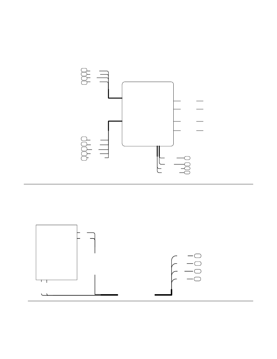
3. Connect the WEBS-VCU and the DIN Rail Terminal Block as shown in Figure 5. If using the IP
paging module (WEBS-CM-2 or VOIP-500 Series Emergency Phone), connect the respective wires
to the WEBS-CM-2 Input port on the WEBS-VCU. If using the analog paging module (WEBS-ZPS)
connect the respective wires to the WEBS-ZPS Input port on the WEBS-VCU. The unused cable
wires should be individually insulated from each other.
38
Paging
Amplifier
WEBS-VCU
M
ic
ro
p
h
o
n
e
In
p
u
t
W
E
B
S
-C
M
-2
/
W
E
B
S
-Z
P
S
In
p
u
t
Audio
Output 1
Power / Trigger
Audio
Output 3
Audio
Output 4
Audio
Output 2
[WHITE]
[GREEN]
[RED]
[BLACK]
[BLACK]
[RED]
[WHITE]
[YELLOW]
–
BARE SHIELD
[GREEN]
RCA CABLE 1
RCA CABLE 2
RCA CABLE 3
RCA CABLE 4
}
39
40
41
42
43
44
45
46
{
{
To DIN Rail
Terminal Block
To DIN Rail
Terminal Block
[RED / BROWN]
[BLACK / GREEN]
[WHITE]
[ORANGE-
WHITE]
7
8
52
54
Figure 5. WEBS-VCU, Paging Amplifier and DIN Rail Terminal Block Connectivity Layout
4. When using WEBS-CM-2 or VOIP-500 Series Emergency Phone make connections to the DIN Rail
Terminal Block as shown in Figure 6.
VOIP-500 /
WEBS-CM-2
A
u
d
io
O
u
tp
u
t
Auxiliary Output
[Dry Contact Closure]
[G
R
E
E
N
]
[W
H
IT
E
]
[RED]
A
u
d
io
L
in
e
L
e
v
e
l
T
w
is
te
d
S
h
ie
ld
e
d
P
a
ir
C
a
b
le
Twisted One Pair Shielded
And One Pair Unshielded Cable
[BLACK]
[RED]
[BLACK]
[WHITE]
[GREEN]
13
14
15
16
}
To DIN Rail Terminal
Block
Figure 6. VOIP-500 / WEBS-CM-2 and DIN Rail Terminal Block Connectivity Layout