Gen a alignment tool provisions – Nexen RPG25A-GE486T 966740 User Manual
Page 9
9
FORM NO. L-21235-G-0413
Alignment Tool
Part #
Figure 7 GEN B ALIGNMENT TOOL
Alignment Tool
Part #
Figure 8 GEN A ALIGNMENT TOOL
The bolt can either pass through the alignment tool
from the top and thread into the machine bed or pass
through the machine bed and thread into the alignment
tool. See Table 1 for bolt sizes depending on method
chosen.
If fastening the alignment tool in place is not possible
or in the case of GEN B, it can also be clamped in
place by placing a small piece of flat stock across the
two alignment tool pins on each rack end and clamping
them down by some other provision.
If fastening or clamping is not possible or in the case
of GEN B, the alignment tool can be manually seated
across the rack joint while pressing it forcefully into
the rack. When the adjacent rack section is properly
spaced, the alignment tool will feel solidly seated when
alternately pushing down on opposite ends of the tool.
If not using the bolt down method, skip to Step 12.
9. Fasten the Alignment Tool to the mounting surface
using customer supplied fasteners while making sure
the face of the alignment tool is fully seated against
the rack face and tighten to the initial torque value in
Table 1.
10. Tighten the second rack’s bolts to 10% of the torque
values in Table 2.
11. Torque the alignment tool to the final torque specified
in Table 1.
12. Torque the second rack to 50% of the torque listed
in Table 2 working from the middle of the rack to the
ends. Then repeat with 100% torque, as specified in
Table 2.
13. Carefully remove the alignment tool, while avoiding
any damage to the rack or alignment tool.
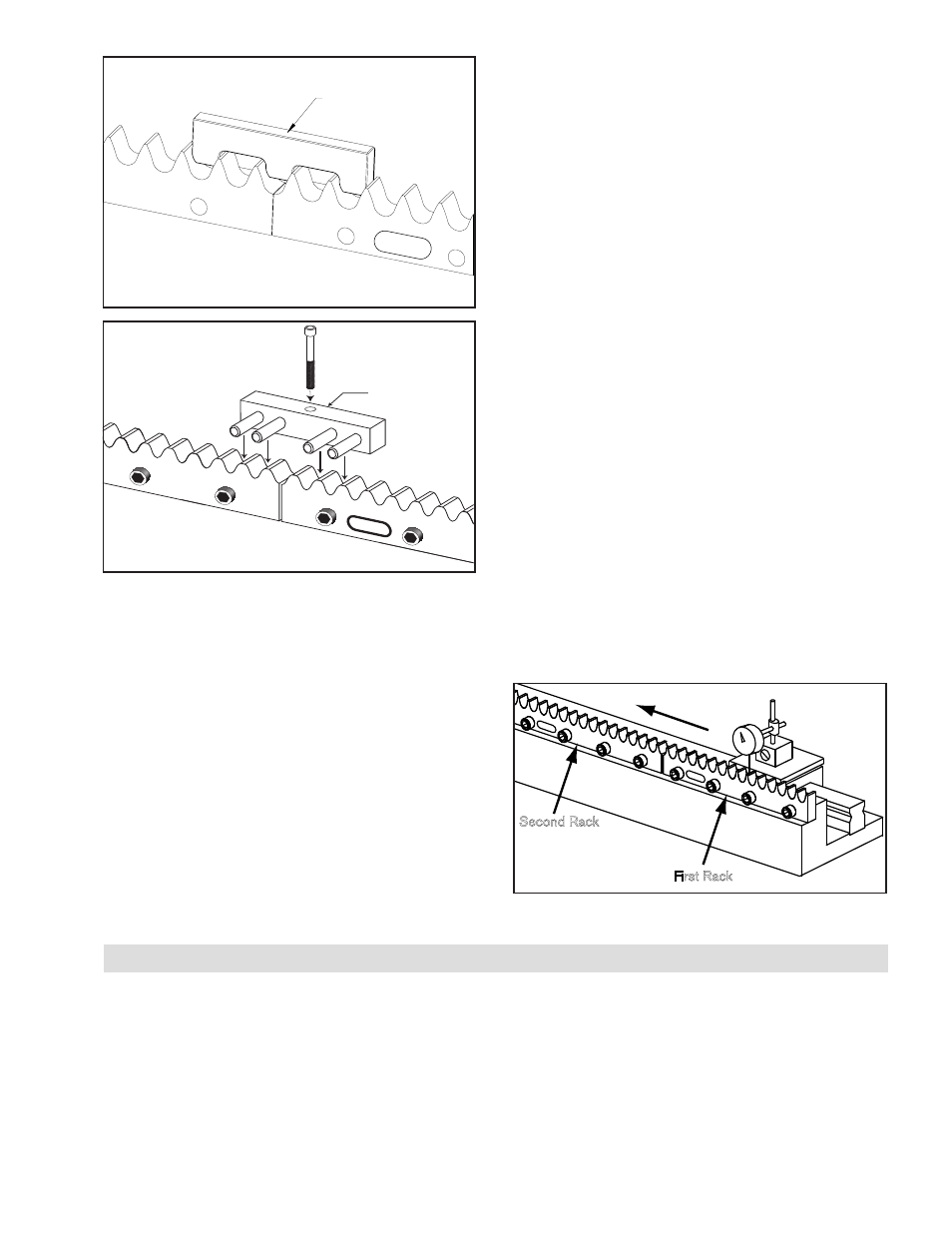
14. Starting on the first rack perform the tooth peak
variance check and extend it to the second rack as
covered in step 6. If the tooth peak variance on the
second rack is out of specifications shim it to match
the first rack. Always reference the runout of additional
rack sections against the first rack installed at the high
point in the run as shown in Figure 9.
15. Repeat Steps 7 through 14 for any additional rack
sections.
Second Rack
First Rack
Part #
Part #
Figure 9
GEN A ALIGNMENT TOOL PROVISIONS
When joining multiple sections of rack it is recommended
that the provisions shown in Figure 10 be used whenever
possible.
In some applications this may not be practical. In these
cases the GEN A alignment tool can be clamped in place
by placing the alignment tool in position across the rack
joint and laying a flat steel bar across the pins and clamping
against the steel bar.
If clamping is not possible or in the case of GEN B, the
alignment tool can be manually seated across the rack
joint while pressing the pins forcefully into the rack teeth.
When the adjoining rack section is properly spaced, no
movement should be felt when alternately pushing down
on opposite ends of the alignment tool.
- RPG20A-GE180T 966734 RPG20A-GE140T 966706 RPG32A-GE0450T 966685 RPG16A-GE400T 966656 RPG20A-GE150T 966615 RPG16A-GE150T 966557 RPG16A-GE936T 966556 RPG4014A-GE192T 966548 RPG4014A-GE072T 966547 RPS25 966679 RPS25 966678 RPS20 966707 RPG32A-GE0760T 966779 ISO9409-064-SS 960855 ISO9409-090 960850 ISO9409-064 960851 ISO9409-200 960854 ISO9409-140 960853 ISO9409-110 960852 RPS40 966543 RPS32 966533 RPS25 966523 RPS20 966513 RPS12 966508 RPS10 966507 RPS16 966503 RPS20 966618 RPS16 966715 RPS16 966687 RPS32 966677 RPS40 966697 RPS4014 966700 RPS25 966673 RPS20 966753 RPS20 966675 RPS20 966781 RPS16 966650 RPS32 966680 RPS4014 966693 RPS40 966690 RPS25 966670 RPS20 966660 RPS16 966850 RPS32 966853 RPS25 966852 RPS4014 966855 RPS40 966854 RPS20 966851 RPS16 966605 RPS16 966606 RPS16 966651 RPS32 966681 RPS16 966654 RPS32 966608 RPS4014 966695 RPS40 966692 RPS16 966652 RPS32 966682 RPS25 966672 RPS20 966662 RPS12 966769 RPS10 966768 RPS16 966777 RPS32 966609 RPS16 966709 RPS25 966671 RPS4014 966694 RPS40 966691 RPS20 966661 RPS16 966800 RPS32 966806 RPS4014 966811 RPS40 966809 RPS16 966801 RPS32 966807 RPS25 966805 RPS20 966803 RPS25 966804 RPS40 966810 RPS40 966808 RPS20 966802 RPS16 966741 RPS16 966742 RPS25 966755 RPS20 966619 RPS4014 966601 RPS40 966631 RPS4014 966647 RPS32 966642 RPS16 966602 RPS32 966632 RPS25 966622 RPS20 966612 RPS25 966621 RPS4014 966646 RPS40 966641 RPS20 966611