Nexen RPG25A-GE486T 966740 User Manual
Page 10
FORM NO. L-21235-G-0413
10
Alignment Tool Mounting Bolt Specifications
RPS
Size
Through Hole
Tapped Hole
Bolt
Size
Tightening Torque
Initial/Final Nm [in-lb]
Thread
Depth
mm [in]
Tightening Torque
Initial/Final Nm [in-lb]
16
M6
1/5 [9/44]
M8
16 [0.63]
1/8 [7/71]
20
M8
1/8 [7/71]
M10
20 [0.79]
1/12 [9/106]
25 & 32
M10
2/28 [18/248]
M12
24 [0.94]
2/30 [18/266]
40 & 4014
M10
3/32 [27/283]
M12
24 [0.94]
3/35 [27/310]
50
M10
3/32 [27/283]
M12
24 [0.94]
3/35 [27/310]
Bolt Type
Mounting Material
Steel
Cast Iron
Aluminum
Rack Mounting Tightening Torque for Socket Head Cap Screws (Class 10.9 or better)
M5
8.2 Nm [73 in-lb]
5.4 Nm [48 in-lb]
4.0 Nm [35 in-lb]
M6
16 Nm [140 in-lb]
10 Nm [89 in-lb]
8 Nm [71 in-lb]
M8
31 Nm [275 in-lb]
20 Nm [177 in-lb]
15 Nm [128 in-lb]
M10
68 Nm [602 in-lb]
45 Nm [398 in-lb]
33 Nm [292 in-lb]
M12
120 Nm [1062 in-lb]
78 Nm [690 in-lb]
58 Nm [513 in-lb]
M16
196 Nm [1735 in-lb]
131 Nm [1160 in-lb]
98 Nm [867 in-lb]
Rack Mounting Tightening Torque for Stainless Steel Screws (Class 8.8 or better)
M5
5 Nm [44 in-lb]
5 Nm [44 in-lb]
4.0 Nm [35 in-lb]
M6
10 Nm [89 in-lb]
10 Nm [89 in-lb]
8 Nm [71 in-lb]
M8
19 Nm [168 in-lb]
19 Nm [168 in-lb]
15 Nm [128 in-lb]
M10
41 Nm [363 in-lb]
41 Nm [363 in-lb]
33 Nm [292 in-lb]
M12
70 Nm [620 in-lb]
70 Nm [620 in-lb]
58 Nm [513 in-lb]
M16
137 Nm [1213 in-lb]
131 Nm [1160 in-lb]
98 Nm [867 in-lb]
Table 2
Table 1
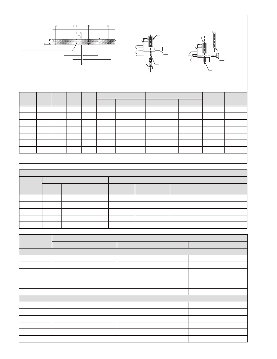
Dimensions apply to standard length rack sections. Cut lengths and customs could vary. Refer to drawings for your specific product
numbers. * Bolt length will vary based on machine design.
A
Second Rack
I Rack Mounting Through Hole (See Table 2)
E
Through Hole
G
Tapped Hole
First Rack
Clearance 0.1 - 0.2 mm
Second Rack Reference Level
B
A
C
E
D
Rack width
Rack Mounting Reference Surface
Positional view of the rack mounting holes (plan view)
F Alignment
Tool Mounting
Bolt
Alignment
Tool
Rack
Segment
Tapped Hole
Mounting of Alignment Tool
GEN A
Through Hole
Mounting of Alignment Tool
GEN A
H Alignment Tool
Mounting Bolt
Alignment Tool
Rack
Segment
J Rack
Mounting Bolt
J Rack
Mounting Bolt
G Tapped Hole
E Through Hole
Figure 10
The dimensions below are nominal in mm and applicable only to standard catalog offerings. Refer to Nexen product
drawings and CAD files for your product numbers for precise dimensions. Special and cut sections of rack may not
conform to these dimensions. The RPS 10 & 12 alignment tools do not bolt down so no data is listed for them below.
RPS
Size
A
B
C
D
Through Hole Mounting
Tapped Hole Mounting
I
J
E
F
G & H
H
16
96
32
16
19.5
9
M8 x 1.25
M6 x 1.00
M6-50
7
M6
20
100
100
50
25.5
11
M10 x 1.50
M8 x 1.25
M6-60
9
M8
25
100
100
50
30.5
14
M12 x 1.75
M10 x 1.50
M10-75
11
M10
32
96
32
16
36.5
14
M12 x 1.75
M10 x 1.50
M10-95
14
M12
40
120
160
80
43.5
14
M12 x 1.75
M10 x 1.50
M10-95
18
M16
4014
80
120
60
54.0
14
M12 x 1.75
M10 x 1.50
M10-95
18
M16
50
62.50 62.50 31.25
54.0
14
M12 x 1.75
M10 x 1.50
M10-95
18
M16
- RPG20A-GE180T 966734 RPG20A-GE140T 966706 RPG32A-GE0450T 966685 RPG16A-GE400T 966656 RPG20A-GE150T 966615 RPG16A-GE150T 966557 RPG16A-GE936T 966556 RPG4014A-GE192T 966548 RPG4014A-GE072T 966547 RPS25 966679 RPS25 966678 RPS20 966707 RPG32A-GE0760T 966779 ISO9409-064-SS 960855 ISO9409-090 960850 ISO9409-064 960851 ISO9409-200 960854 ISO9409-140 960853 ISO9409-110 960852 RPS40 966543 RPS32 966533 RPS25 966523 RPS20 966513 RPS12 966508 RPS10 966507 RPS16 966503 RPS20 966618 RPS16 966715 RPS16 966687 RPS32 966677 RPS40 966697 RPS4014 966700 RPS25 966673 RPS20 966753 RPS20 966675 RPS20 966781 RPS16 966650 RPS32 966680 RPS4014 966693 RPS40 966690 RPS25 966670 RPS20 966660 RPS16 966850 RPS32 966853 RPS25 966852 RPS4014 966855 RPS40 966854 RPS20 966851 RPS16 966605 RPS16 966606 RPS16 966651 RPS32 966681 RPS16 966654 RPS32 966608 RPS4014 966695 RPS40 966692 RPS16 966652 RPS32 966682 RPS25 966672 RPS20 966662 RPS12 966769 RPS10 966768 RPS16 966777 RPS32 966609 RPS16 966709 RPS25 966671 RPS4014 966694 RPS40 966691 RPS20 966661 RPS16 966800 RPS32 966806 RPS4014 966811 RPS40 966809 RPS16 966801 RPS32 966807 RPS25 966805 RPS20 966803 RPS25 966804 RPS40 966810 RPS40 966808 RPS20 966802 RPS16 966741 RPS16 966742 RPS25 966755 RPS20 966619 RPS4014 966601 RPS40 966631 RPS4014 966647 RPS32 966642 RPS16 966602 RPS32 966632 RPS25 966622 RPS20 966612 RPS25 966621 RPS4014 966646 RPS40 966641 RPS20 966611