Nexen RPG25A-GE486T 966740 User Manual
Page 15
15
FORM NO. L-21235-G-0413
Table 6
Screw
Tightening Torque
Nm [in-lb]
Preloader Screw
All Models
-
1.7 [15] Max
Shoulder Screws (Mtg. Plate)
RPS-PRE-064
M8 x 1.25
40 [350]
RPS-PRE-090
M8 x 1.25
40 [350]
RPS-PRE-110
M8 x 1.25
40 [350]
RPS-PRE-140
M8 x 1.25
40 [350]
RPS-PRE-200
M12 x 1.75
120 [1060]
Gearhead Screws (Mtg. Plate)
RPS-PRE-064
M4 x 0.7
5.3 [47]
RPS-PRE-090
M5 x 0.8
10 [88]
RPS-PRE-110
M5 x 0.8
10 [88]
RPS-PRE-140
M6 x 1.0
17.5 [155]
RPS-PRE-200
M8 x 1.25
40 [354]
Preloader Mtg. Screws (2x)
All Models
M6 x 1.0
17.5 [155]
3. Verify pinion rotational axis is as close to 90° from the
rack run axis, the pinion rotational axis is also parallel
with the tooth tops or rack mounting surface, and the
rack is centered between the pinion bearing flanges
as shown in Figure 1.
4. Rotate the preload adjustment screw clockwise to
separate the pinion from the rack. This will ensure
that clearance is initially present. Then seat the pinion
into contact by turning the preload adjustment screw
counterclockwise until a slight resistance is felt and
then back the screw off 1/8 of a turn. This step is
critical to prepare for preload settings.
5. Place a magnetic base dial indicator on the movable
carriage, and locate its probe on the OD of the pinion
flange such that it measures in the direction of preload
travel.
6. Apply the preload of 0.010 - 0.015 mm [0.0004
- 0.0006 in] with the preload application screw(s)
and then tighten the preload lockdown bolts to
their recommended torques. See Table 6 for Nexen
Preloader System torque values. Typically the preload
will change slightly when the preloader lockdown bolts
are tightened. If tightening the preload bolts causes
the amount of preload to fall outside of specifications
record how much it changed when tightening the
preloader lock down bolts then loosen the preloading
system and repeat the preloading procedure but
adjust the initial preload (more or less) by the recorded
preload deviation. This procedure will ensure that
when the preloader lockdown bolts are tightened the
amount of preload should fall within specifications.
7. With the pinion preloaded to specifications manually
traverse the carriage down the run by hand (if possible)
checking for smoothness and uniformity of resistance.
If manually applied motion is not possible, use the
servo motor to traverse the carriage along the run, with
just enough torque output to move it while looking and
listening for resistance to motion.
Proper roller to tooth meshing is critical and can be verified
by two methods depending on which you find easier to
interpret:
Option 1: Apply a slow drying machinists dye to the pinion
rollers and move the RPS system back and forth over a
short distance (about 1/2 meter). It is important the dye
remain wet so it transfers to the rack teeth and is not
depleted. Analyze the dye pattern transferred to the teeth.
If the meshing geometry is good the dye will be spread
evenly all the way across the tooth face over the middle
2/3 - 3/4 of the teeth with none at the top and bottom. If
this section is properly aligned clean off dye residue and
repeat as necessary to verify the RPS alignment over the
entire length of travel. See Figure 20.
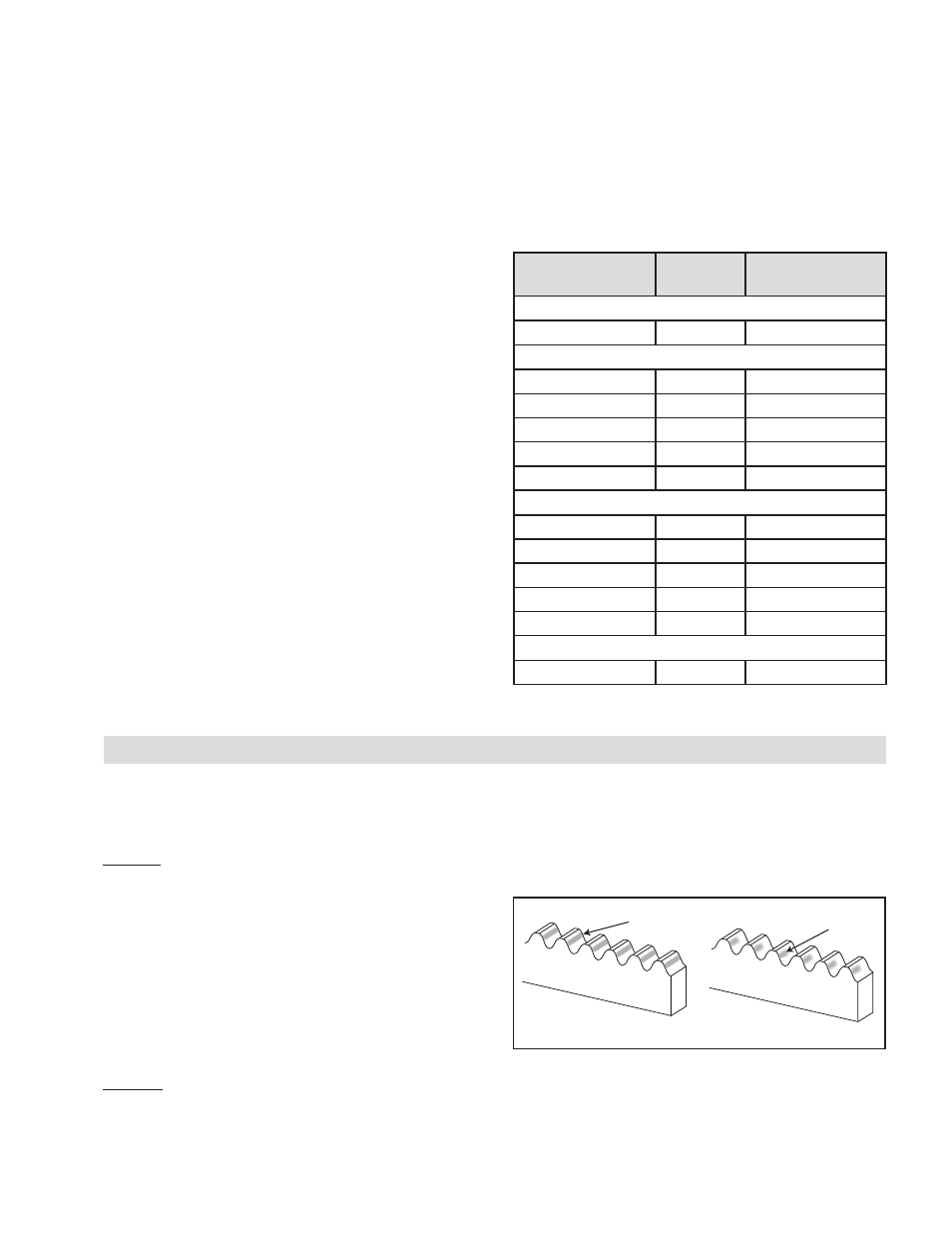
Option 2: Apply a small amount of high contrast grease
to each rack tooth face over 1/2 meter of rack. Operate
the RPS system back and forth over this 1/2 meter of
travel. If the meshing geometry is good the grease will be
Good Alignment
Poor Alignment
Contact Pattern
Contact Pattern
Figure 20
completely wiped away all the way across the tooth face
over the middle 2/3 - 3/4 of the teeth with some remaining
at the top and bottom. If this section is properly aligned
clean off grease with a solvent and repeat as necessary
to verify the RPS alignment over the entire length of travel
as shown in Figure 20.
SYSTEM ALIGNMENT VERIFICATION
If the dye or grease contact pattern indicates a meshing
problem, diagnose the problem, correct it, and then repeat
the Applying Preload and System Alignment Verification
procedures.
- RPG20A-GE180T 966734 RPG20A-GE140T 966706 RPG32A-GE0450T 966685 RPG16A-GE400T 966656 RPG20A-GE150T 966615 RPG16A-GE150T 966557 RPG16A-GE936T 966556 RPG4014A-GE192T 966548 RPG4014A-GE072T 966547 RPS25 966679 RPS25 966678 RPS20 966707 RPG32A-GE0760T 966779 ISO9409-064-SS 960855 ISO9409-090 960850 ISO9409-064 960851 ISO9409-200 960854 ISO9409-140 960853 ISO9409-110 960852 RPS40 966543 RPS32 966533 RPS25 966523 RPS20 966513 RPS12 966508 RPS10 966507 RPS16 966503 RPS20 966618 RPS16 966715 RPS16 966687 RPS32 966677 RPS40 966697 RPS4014 966700 RPS25 966673 RPS20 966753 RPS20 966675 RPS20 966781 RPS16 966650 RPS32 966680 RPS4014 966693 RPS40 966690 RPS25 966670 RPS20 966660 RPS16 966850 RPS32 966853 RPS25 966852 RPS4014 966855 RPS40 966854 RPS20 966851 RPS16 966605 RPS16 966606 RPS16 966651 RPS32 966681 RPS16 966654 RPS32 966608 RPS4014 966695 RPS40 966692 RPS16 966652 RPS32 966682 RPS25 966672 RPS20 966662 RPS12 966769 RPS10 966768 RPS16 966777 RPS32 966609 RPS16 966709 RPS25 966671 RPS4014 966694 RPS40 966691 RPS20 966661 RPS16 966800 RPS32 966806 RPS4014 966811 RPS40 966809 RPS16 966801 RPS32 966807 RPS25 966805 RPS20 966803 RPS25 966804 RPS40 966810 RPS40 966808 RPS20 966802 RPS16 966741 RPS16 966742 RPS25 966755 RPS20 966619 RPS4014 966601 RPS40 966631 RPS4014 966647 RPS32 966642 RPS16 966602 RPS32 966632 RPS25 966622 RPS20 966612 RPS25 966621 RPS4014 966646 RPS40 966641 RPS20 966611