General design guidelines, W1/2 w, Installation – Nexen RPG25A-GE486T 966740 User Manual
Page 7
7
FORM NO. L-21235-G-0413
A
Rack
B
0.03 mm A
0.03 mm B
//
0.03 mm
A
//
0.03 mm
B
0.03 mm
A
//
Parallel
Rack
90˚
± 0.1°
Pinion
Shaft
GENERAL DESIGN GUIDELINES
Figure 2 Tolerances
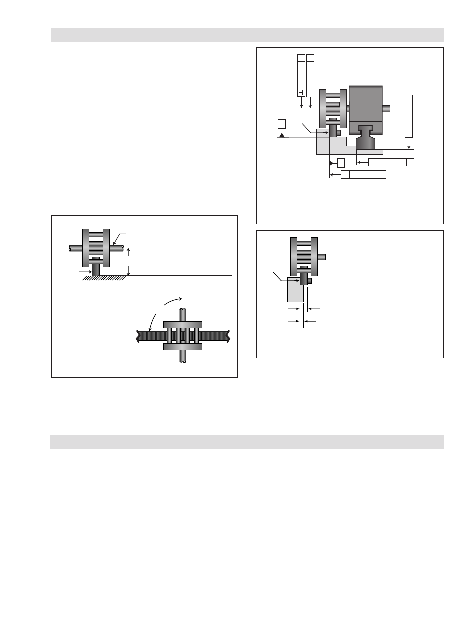
In order to minimize backlash , obtain the highest positional
accuracy, and minimize wear on the rack, the RPS system
must be installed on a rigid, straight, flat mounting surface
with the tolerances shown in Figure 2.
The following requirements must be met to ensure proper
RPS operation:
a) Mount a linear guide rail on a surface parallel to the
RPS rack mounting surface with the same flatness as
the rack mounting surface ash shown in Figure 2.
b) The pinion shaft must be parallel (0.03 mm [0.001 in])
to the rack mounting surface opposite the rack teeth
and the angle between the pinion shaft and the face
of the rack must be 90° ±0.1° maximum as shown in
Figure 1).
Figure 1 Pinion Alignment Requirements
Systems may be mounted at any angle as long as the rack,
guiding system and mounting surface remain parallel with
the shaft at a 90° angle from the rack.
This distance must remain
parallel within 0.03 mm
[0.001 in]
Additional dimensional detail can be found in
Nexen’s product drawings.
The rack must sit on a step at
least one half the width of the
rack for proper support. The
rack should not be supported
by fasteners alone. Pinning the
rack to its mounting surface is
not recommended.
Rack
W
1/2 W
c) The pinion shaft must be supported adequately to
ensure full contact of the pinion rollers along the face
of rack teeth.
Figure 3 Rack Support Requirements
INSTALLATION
The mounting surface for both the rack and the guiding
system must be parallel within the specifications shown
in Figure 2. This parallelism requirement is best achieved
by machining the mounting locations for both the guiding
system and rack in the same machining operation. (Refer
to PROPER SYSTEM ALIGNMENT and Figures 1 and 2
for Possible Mounting Configurations.)
Nexen recommends orienting the rack teeth downward or
to the side so it minimizes the possibility of debris collecting
on the teeth and causing meshing interference. The rack
has 5 reference surfaces and includes all sides except the
side with the product number. The non-reference face
with the product number should not be placed against
the machine bed surfaces. Any rack ends that have been
cut must be located at the end of the run; the pinion must
not cross cut rack ends.
- RPG20A-GE180T 966734 RPG20A-GE140T 966706 RPG32A-GE0450T 966685 RPG16A-GE400T 966656 RPG20A-GE150T 966615 RPG16A-GE150T 966557 RPG16A-GE936T 966556 RPG4014A-GE192T 966548 RPG4014A-GE072T 966547 RPS25 966679 RPS25 966678 RPS20 966707 RPG32A-GE0760T 966779 ISO9409-064-SS 960855 ISO9409-090 960850 ISO9409-064 960851 ISO9409-200 960854 ISO9409-140 960853 ISO9409-110 960852 RPS40 966543 RPS32 966533 RPS25 966523 RPS20 966513 RPS12 966508 RPS10 966507 RPS16 966503 RPS20 966618 RPS16 966715 RPS16 966687 RPS32 966677 RPS40 966697 RPS4014 966700 RPS25 966673 RPS20 966753 RPS20 966675 RPS20 966781 RPS16 966650 RPS32 966680 RPS4014 966693 RPS40 966690 RPS25 966670 RPS20 966660 RPS16 966850 RPS32 966853 RPS25 966852 RPS4014 966855 RPS40 966854 RPS20 966851 RPS16 966605 RPS16 966606 RPS16 966651 RPS32 966681 RPS16 966654 RPS32 966608 RPS4014 966695 RPS40 966692 RPS16 966652 RPS32 966682 RPS25 966672 RPS20 966662 RPS12 966769 RPS10 966768 RPS16 966777 RPS32 966609 RPS16 966709 RPS25 966671 RPS4014 966694 RPS40 966691 RPS20 966661 RPS16 966800 RPS32 966806 RPS4014 966811 RPS40 966809 RPS16 966801 RPS32 966807 RPS25 966805 RPS20 966803 RPS25 966804 RPS40 966810 RPS40 966808 RPS20 966802 RPS16 966741 RPS16 966742 RPS25 966755 RPS20 966619 RPS4014 966601 RPS40 966631 RPS4014 966647 RPS32 966642 RPS16 966602 RPS32 966632 RPS25 966622 RPS20 966612 RPS25 966621 RPS4014 966646 RPS40 966641 RPS20 966611