Non-simultaneous and simultaneous operation, Page 7 – Bradford White DB-80R3DS User Manual
Page 7
Non-Simultaneous and Simultaneous Operation
Double element electric water heaters are designed to operate in a Non-Simultaneous or Simultaneous mode.
Non-Simultaneous Mode: Allows only one heating element to operate at a time. For example, when the tank is cold,
the upper element is energized first, heating the top of the tank. Only when the upper thermostat is satisfied, the upper
element is de-energized and power is directed to the lower thermostat, energizing the lower element and heating the
bottom portion of the tank until the lower thermostat is satisfied. As hot water is drawn off the tank, it is replaced with
cold water delivered through the dip tube to the bottom of the tank. The bottom of the tank cools, the lower thermostat
will call for heat energizing the lower element. If enough hot water is drawn from the tank, the top portion of the tank
cools and the upper thermostat will call for heat, de-energizing the lower element and allowing only the top element to
energize until the upper thermostat is satisfied.
Simultaneous mode: allows both heating elements to operate at the same time. That is, if either thermostat (upper or
lower) is calling for heat, the corresponding heating element is energized independent of the other.
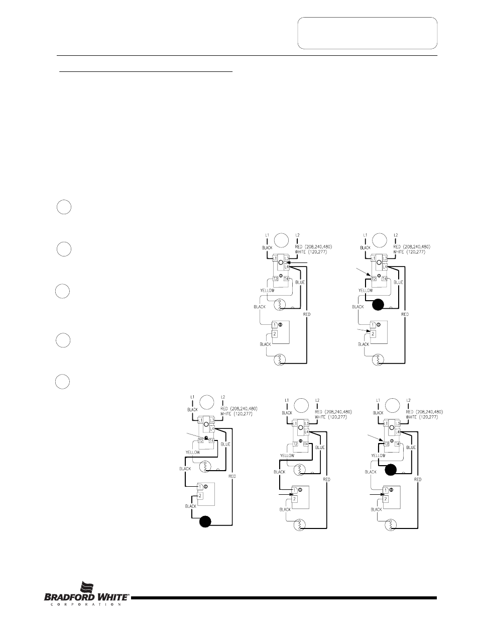
SEQUENCE OF OPERATION
Sequence of Operation- Double Element, Non-Simultaneous Operation, Single Phase.
Line voltage is applied across terminals
L1 & L3 of the upper thermostat. ECO is
closed, so there is voltage at terminal L4
and to one side of the upper and lower
elements.
Tank is cold therefore both thermostats
are closed at terminal T2 & 2 (calling for heat). The
circuit is complete through the upper thermostat
only, allowing current to flow through upper
element.
1
2
1
2
ECO
Closed
Thermostat closed
at terminal T2
When upper thermostat is satisfied, it opens at
terminal T2 interrupting current flow through upper
element, and closes at terminal T4 allowing voltage
to pass to terminal 1 of lower thermostat. This
completes the circuit through the lower thermostat
and allows current flow through lower element.
3
3
Thermostat closed
at terminal T4
4
Thermostat open
between terminals
1 and 2
Upper
T’stat
Upper
Element
Upper
T’stat
Upper
Element
Lower
T’stat
Lower
Element
Lower
T’stat
Lower
Element
When the lower thermostat is satisfied, it opens at
terminal 2 interrupting current flow through lower
element. The system is now in stand-by mode
waiting for the next call for heat
4
The lower thermostat/element
combination will generally
cycle on and off more often
then the upper. In some cases,
such as a cold tank or in high
demand periods, the upper
thermostat will call for heat
(opening at terminal
T4 and closing at
terminal T2) prior to the lower
thermostat being satisfied. This
will interrupt current flow
through the lower thermostat
and element and allow current
to flow through the upper
element only. When the upper
thermostat is satisfied, it
resumes operation as
described in sequence #3
above.
5
5
Thermostat closed
between terminals
1 and 2
Upper
T’stat
Upper
Element
Lower
T’stat
Lower
Element
Upper
T’stat
Upper
Element
Lower
T’stat
Lower
Element
Upper
T’stat
Upper
Element
Lower
T’stat
Lower
Element
Thermostat closed
at terminal 2
Thermostat closed
at terminal T2
Page 7
7
- LD-WH30L3-1 LD-WH20L3-1 LD-WH12U3-1 LD-WH6U3-1 LD-50L3-3 LD-40L3-3 LD-30L3-3 LD-20L3-3 LD-30U3-1 LD-20U3-1 LD-15U3-1 LD-12UT3-1 LD-10U3-1 LD-6U3-1 LD-120R3-3 LD-80R3-3 LD-65R3-3 LD-50S3-3 LD-40S3-3 LD-30R3-3 M-2-WH30L6SS M-1-WH20L6SS M-1-WH12U6SS M-1-WH6U6SS M-2-30U6SS M-1-20U6SS M-1-15U6SS M-1-12UT6SS M-1-12U6SS