Oa ) + (tr, Ra ) =t, 48h e, h j – Carrier 48HJ004---007 User Manual
Page 27
27
activation to allow the dampers to open. This delay allows the
damper to reach the appropriate position to avoid unnecessary fan
overload.
Minimum Position Control
There is a minimum damper position potentiometer on the
EconoMi$er IV controller. (See Fig. 42.) The minimum damper
position maintains the minimum airflow into the building during
the occupied period.
When using demand ventilation, the minimum damper position
represents the minimum ventilation position for VOC (volatile
organic compound) ventilation requirements. The maximum
demand ventilation position is used for fully occupied ventilation.
When demand ventilation control is not being used, the minimum
position potentiometer should be used to set the occupied
ventilation position. The maximum demand ventilation position
should be turned fully clockwise.
Adjust the minimum position potentiometer to allow the
minimum amount of outdoor air, as required by local codes, to
enter the building. Make minimum position adjustments with at
least 10_F temperature difference between the outdoor and
return-air temperatures.
To determine the minimum position setting, perform the
following procedure:
1. Calculate the appropriate mixed air temperature using the
following formula:
(T
O x
OA
) + (TR
x
RA
) =T
M
100
100
T
O
= Outdoor-Air Temperature
OA = Percent of Outdoor Air
T
R
= Return-Air Temperature
RA = Percent of Return Air
T
M
= Mixed-Air Temperature
As an example, if local codes require 10% outdoor air during
occupied conditions, outdoor-air temperature is 60_F, and
return-air temperature is 75_F.
(60 x .10) + (75 x .90) = 73.5_F
2. Disconnect the supply air sensor from terminals T and T1.
3. Ensure that the factory-installed jumper is in place across
terminals P and P1. If remote damper positioning is being
used, make sure that the terminals are wired according to
Fig. 36 and that the minimum position potentiometer is
turned fully clockwise.
4. Connect 24 vac across terminals TR and TR1.
5. Carefully adjust the minimum position potentiometer
until the measured supply air temperature matches the
calculated value.
6. Reconnect the mixed air sensor to terminals T and T1.
Remote control of the EconoMi$er IV damper is desirable when
requiring
additional
temporary
ventilation.
If
a
field-supplied remote potentiometer (Honeywell part number
S963B1128) is wired to the EconoMi$er IV controller, the
minimum position of the damper can be controlled from a remote
location.
To control the minimum damper position remotely, remove the
factory-installed jumper on the P and P1 terminals on the
EconoMi$er IV controller. Wire the field-supplied potentiometer
to the P and P1 terminals on the EconoMi$er IV controller. (See
Fig. 46.)
Damper Movement
Damper movement from full open to full closed (or vice versa)
takes 2
1
/
2
minutes.
Thermostats
The EconoMi$er IV control works with conventional thermostats
that have a Y1 (cool stage 1), Y2 (cool stage 2), W1 (heat stage
1), W2 (heat stage 2), and G (fan). The EconoMi$er IV control
does not support space temperature sensors. Connections are
made at the thermostat terminal connection board located in the
main control box.
LED ON
LED ON
LED ON
LED ON
LED OFF
19
18
LED OFF
LED OFF
LED OFF
17
16
15
14
13
12
11
10
9
40
45
50
55
60
65
70
75
80
85
90
95 100
DEGREES FAHRENHEIT
mA
D
C
B
A
C06035
Fig. 43
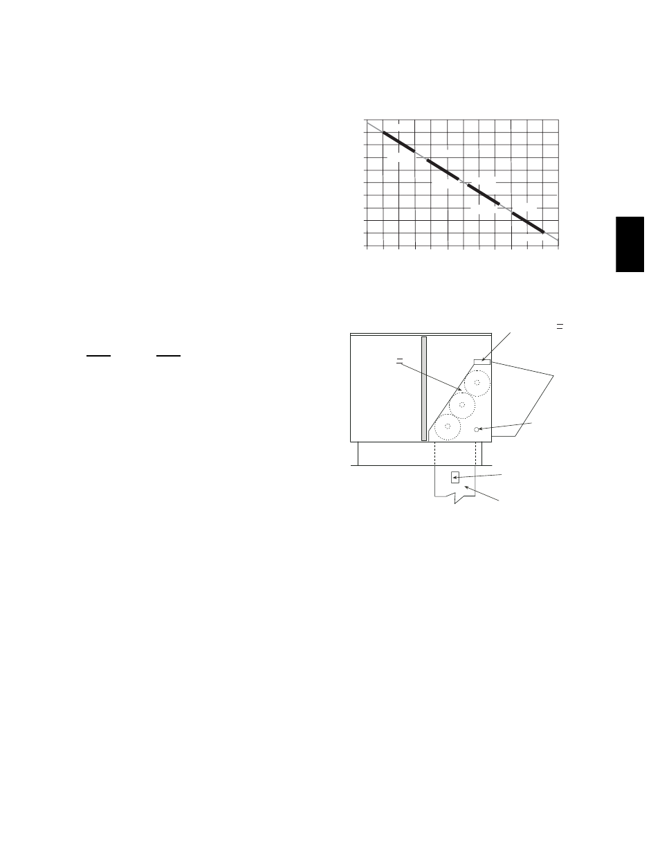
--- Outside Air Temperature
Changeover Set Points
ECONOMI$ER IV
ECONOMI$ER IV
CONTROLLER
GROMMET
RETURN AIR
SENSOR
RETURN DUCT
(FIELD-PROVIDED)
C06036
Fig. 44
--- Return Air Temperature or Enthalpy
Sensor Mounting Location
Occupancy Control
The factory default configuration for the EconoMi$er IV control
is occupied mode. Occupied mode is provided by the black
jumper from terminal TR to terminal N. When unoccupied mode
is desired, install a field-supplied timeclock function in place of
the jumper between TR and N. (See Fig. 36.) When the timeclock
contacts are closed, the EconoMi$er IV control will be in
occupied mode. When the timeclock contacts are open (removing
the 24-v signal from terminal N), the EconoMi$er IV will be in
unoccupied mode.
48H
E,
H
J