48h e, h j – Carrier 48HJ004---007 User Manual
Page 12
12
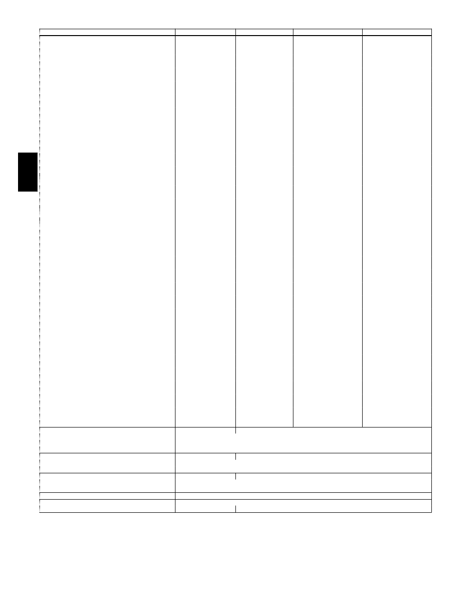
TABLE 2 — PHYSICAL DATA 48HE (cont)
BASE UNIT 48HE
HD/E/F003
HE/F/H/K/M/N004
HD/E/F/G/H/K/L/M/N005
HD/E/F/G/H/K/L/M/N006
FURNACE SECTION
Rollout Switch Cutout Temp (F)†
195
195
195
195
Burner Orifice Diameter (in. ...drill size)**
Natural Gas — Std*
HJE .113...33
HJD .113...33
HJD .113...33
HEE .089...43
HJF .113...33
HJE .113...33
HJE .113...33
—
HJF .129...30
HJF .129...30
—
HJH .113...33
HJG .113...33
HJG .113...33
—
HJK .113...33
HJH .113...33
HJH .113...33
—
—
HJK .129...30
HJK .129...30
HEM .089...43
HJM .102...38
HJL .102...38
HJL .102...38
—
HJN .102...38
HJM .102...38
HJM .102...38
—
—
HJN .116...32
HJN .116...32
Liquid Propane — Alt††
HEE .073...49
HJE .089...43
HJD .089...43
HJD .089...43
HJF .089...43
HJE .089...43
HJE .089...43
—
HJF .104...37
HJF .104...37
—
HJH .089...43
HJG .089...43
HJG .089...43
—
HJK .089...43
HJH .089...43
HJH .089...43
—
—
HJK .102...37
HJK .104...37
—
—
—
—
Thermostat Heat Anticipator Setting (amps)
208/230/460/575 v
First Stage
.14
.14
.14
.14
Second Stage
.14
.14
.14
.14
Gas Input (Btuh)
First Stage/Second Stage
HEE 50,000/---
HEE||
50,000/ 72,000
HED|| 50,000/ 72,000
HED|| 50,000/ 72,000
HEF||
82,000/115,000
HEE|| 82,000/115,000
HEE|| 82,000/115,000
—
HEF|| 120,000/150,000
HEF|| 120,000/150,000
—
HEH*** —/ 72,000
HEG*** —/ 72,000
HEG*** —/ 72,000
—
HJK***—/115,000
HEH*** —/115,000
HEH*** —/115,000
—
—
HEK*** —/150,000
HEK*** —/150,000
—
HEM††† —/ 60,000
HEL††† —/ 60,000
HEL††† —/ 60,000
—
HEN††† —/ 90,000
HEM††† —/ 90,000
HEM†††—/ 90,000
—
—
HEN††† —/120,000
HEN††† —/120,000
Efficiency (Steady State) (%)
HEE 81
HEE 82.8
HED 82.8
HED 82.8
HEF 80
HEE 81
HEE 81
—
HEF 80.4
HEF 80.4
—
HEH 82
HEG 82
HEG 82
—
HEK 80
HEH 81
HEH 81
—
—
HEK 80
HEK 80
—
HEM 80.2
HEL 80.2
HEL 80.2
HEM 81
HEN 81
HEM 81
HEM 81
—
—
HEN 80.7
HEN 80.7
Temperature Rise Range
HEE 25-55
HED 25-25
HED 25-55
HEE 25-65
HEF 55-85
HEE 35-65
HEE 35-65
—
HEF 50-80
HEF 50-80
—
HEH 25-55
HEG 25-55
HEG 25-55
—
HEK 55-85
HEH 35-65
HEH 35-65
—
—
HEK 50-80
HEK 50-80
—
HEM 20-50
HEL 20-50
HEL 20-50
—
HEN 30-60
HEM 30-60
HEM 30-60
—
—
HEN 40-70
HEN 40-70
Manifold Pressure (in. wg)
Natural Gas — Std
3.5
3.5
3.5
3.5
Liquid Propane — Alt††
3.5
3.5
3.5
3.5
Maximum Static Pressure (in. wg)
1.0
1.0
1.0
1.0
Field Gas Connection Size (in.)
1
/
2
1
/
2
1
/
2
1
/
2
HIGH-PRESSURE SWITCH (psig)
Standard Compressor Internal Relief
450 ± 50
Cutout
428
Reset (Auto.)
320
LOSS-OF-CHARGE SWITCH (Liquid LIne) (psig)
Cutout
7 ± 3
Reset (Auto.)
22 ± 5
FREEZE PROTECTION THERMOSTAT
Opens (F)
30 ± 5
Closes (F)
45 ± 5
OUTDOOR-AIR INLET SCREENS
Cleanable. Screen quantity and size varies with option selected.
RETURN-AIR FILTERS
Throwaway
Quantity...Size (in.)
2...16 x 25 x 2
LEGEND
Bhp — Brake Horsepower
*Stainless steel models use same orifices as equivalent standard unit.
†Indicates automatic reset.
**≤72,000 Btuh heat input units have 2 burners. 90,000 and
120,000 Btuh heat
input units have 3 burners. 115,000 Btuh heat input units and 150,000 Btuh Heat
input units have 3 burners.
††An LP kit is available as an accessory. An LP conversion kit should not be used on a
low NOx unit because then it can no longer be classified as a Low NOx unit. The
Low NOx requirement only applies to natural gas units.
Three-phase standard models have heating inputs as shown. Single-phase standard
models have one-stage heating with heating input values as shown in heatin capac-
ity tables.
***These units do NOT meet the California low NOx requirements.
†††California SCAQMD compliant low NO
x
models have combustion products that are
controlled to 40 nanograms per joule or less.
48H
E,
H
J