48h e, h j – Carrier 48HJ004---007 User Manual
Page 25
25
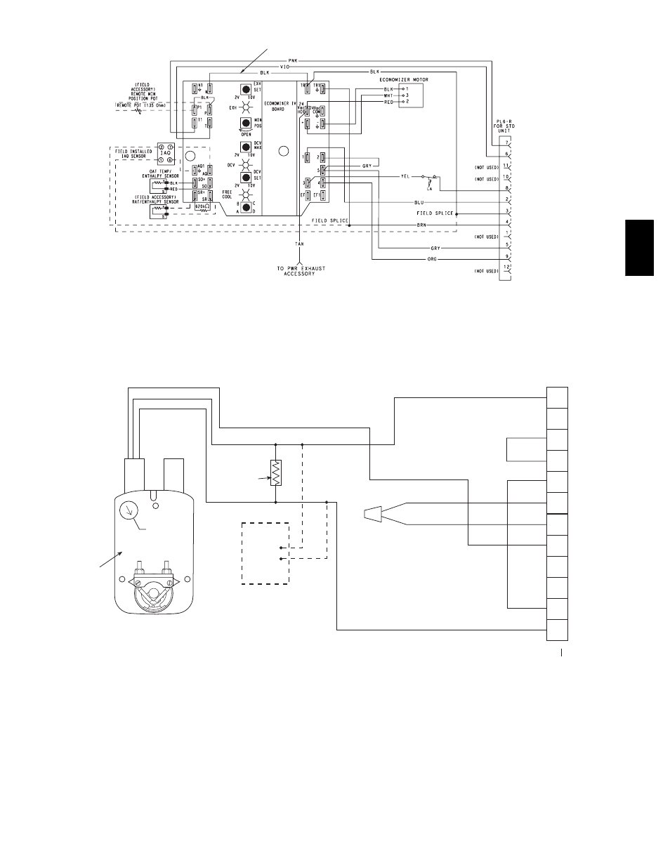
FOR OCCUPANCY CONTROL
REPLACE JUMPER WITH
FIELD-SUPPLIED TIME CLOCK
LEGEND
DCV— Demand Controlled Ventilation
IAQ — Indoor Air Quality
LA — Low Ambient Lockout Device
OAT — Outdoor-Air Temperature
POT — Potentiometer
RAT — Return-Air Temperature
Potentiometer Defaults Settings:
Power Exhaust Middle
Minimum Pos.
Fully Closed
DCV Max.
Middle
DCV Set
Middle
Enthalpy
C Setting
NOTES:
1. 620 ohm, 1 watt 5% resistor should be removed only when using differential
enthalpy or dry bulb.
2. If a separate field-supplied 24 v transformer is used for the IAQ sensor power
supply, it cannot have the secondary of the transformer grounded.
3. For field-installed remote minimum position POT, remove black wire jumper
between P and P1 and set control minimum position POT to the minimum
position.
C06028
Fig. 36
--- EconoMi$er IV Wiring
4
3
5
2
8
6
7
1
10
11
9
12
PINK
VIOLET
BLACK
BLUE
YELLOW
NOTE 1
NOTE 3
RUN
500 OHM
RESISTOR
-
+
OPTIONAL CO
SENSOR 4 - 20 mA
OUTPUT
50HJ540573
ACTUATOR
ASSEMBLY
RED
WHITE
ECONOMISER2 PLUG
DIRECT DRIVE
ACTUATOR
2
NOTES:
1. Switch on actuator must be in run position for economizer to operate.
2. PremierLink™ control requires that the standard 50HJ540569 outside-air sensor be replaced by either the CROASENR001A00 dry bulb sensor or HH57A077
enthalpy sensor.
3. 50HJ540573 actuator consists of the 50HJ540567 actuator and a harness with 500-ohm resistor.
C06029
Fig. 37
--- EconoMi$er2 with 4 to 20 mA Control Wiring
Outdoor Enthalpy Changeover
For enthalpy control, accessory enthalpy sensor (part number
HH57AC078) is required. Replace the standard outdoor dry bulb
temperature sensor with the accessory enthalpy sensor in the same
mounting location. (See Fig. 29.) When the outdoor air enthalpy
rises above the outdoor enthalpy changeover set point, the
outdoor-air damper moves to its minimum position. The outdoor
enthalpy changeover set point is set with the outdoor enthalpy set
point potentiometer on the EconoMi$er IV controller. The set
points are A, B, C, and D. (See Fig. 45.) The factory-installed
620-ohm jumper must be in place across terminals SR and SR+
on the EconoMi$er IV controller. (See Fig. 29 and 46.)
48H
E,
H
J