Printer – Welch Allyn Video Colposcope - User Manual User Manual
Page 18
12
Components
Welch Allyn Video Colposcope
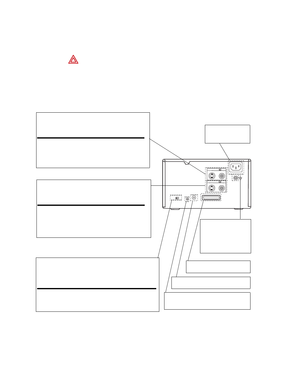
Printer
WARNING If peripheral devices (example: monitor, video printer, VCR ,other) do
not comply with IEC 60601-1-1, they must be kept out of the patient area (6 feet
minimum from patient).
Note
For detailed instructions, please refer to the printer operation manual that has
been provided by the manufacturer. Printer shown is SONY UP-20; this is for
reference only.
NTSC
PAL
REMOTE
1
2
~ AC IN
RS-2232C
INPUT
OUTPUT
S-VIDEO
S-VIDEO
VIDEO
VIDEO
Input Connectors. To connect the video equipment supplying the
source image.
Connector
Connectable Equipment
S-VIDEO
Equipment with a S-Video (Y/C) output
connector
VIDEO
Equipment with a composite video signal
output connector.
Output Connectors. To connect the video monitor. Refer to “Important
safeguards/notices for use in the medical environments”
Connector
Connectable Equipment
S-VIDEO
Video Monitor with a S-Video (Y/C)
separated input connector
VIDEO
Video Monitor with a composite video signal
input connector.
~ AC IN. To connect the
printer to a wall outlet with
the supplied cord.
Equipotential Ground
Terminal Connector. To
connect to the equipotential
plug to bring the various parts of
a system to the same potential.
RS-232C Connector. To connect the
Video Colposcope to control the printer.
NTSC/PAL (TV) Selector. Set this selector according to the TV system of the
input signal. If you change this setting, turn the printer power off and then back
on again.
Selector position
When
NTSC
NTSC system video equipment is connected.
PAL
PAL system video equipment is connected.
Remote 1 Connector. To connect an RM-5500
Remote Control Unit (not supplied) to be used as a
wired remote control unit.
Remote 2 Connector. To connect an RM-91
Remove Control Unit (not supplied).