Thingmagic, a division of trimble, Do not reflow solder with this configuration – ThingMagic Micro Hardware User Manual
Page 40
D
C
B
A
4
3
2
1
D
C
B
A
4
3
2
1
This drawing contains information that
is proprietary and confidential to
ThingMagic, Inc, and should not be
used without written permission.
ThingMagic, A Division of Trimble
Four Cambridge Center, 12
th
Floor, Cambridge, MA 02142 866-833-4069
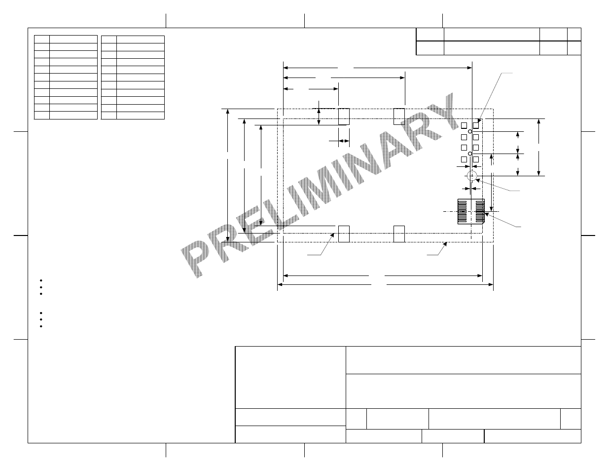
M6e-Micro Module Integration
Flip Mounting Option
SIZE
DWG NO
REV
A
850-0005-01
X8
SCALE
2:1
SHEET
3 OF 5
REV.
DESCRIPTION
DATE
BY
DRAWN BY
R. Herold
DATE
4/9/12
01
Initial Release
RH
Pin
1
3
5
7
9
11
13
15
17
19
Function
Vin
Vin
Gnd
Gnd
USB 5VSENSE
GPIO1
GPIO2
RS232 RX
RS232 TX
Shutdown
0.100 typ
0.150 typ
Optional 0.110"D
Mounting Hole
Pin
2
4
6
8
10
12
14
16
18
20
Function
Vin
Vin
Gnd
Gnd
NC
USB DP
USB DM
NC
NC
Ext Reset
DO NOT REFLOW
SOLDER WITH THIS
CONFIGURATION!
0.910
Component
Keepout
Module
Outline
0.500
1.100
1.030
0.515
0.200
0.200
1.708
0.018
0.523
Footprint for
MOLEX 52991-20
Connector
0.010
Mating Connector: Molex 52991-20
Footprint for
Lighthorse
LTI-IPXSF54GT
Connector
Antenna 1
Antenna 2
I/O
Note: For this configuration, antenna connections may be made either via U.FL board-to-
board connectors as specified above OR via U.FL cables that go directly to the antenna.
The latter is preferable if the antenna is not part of the board assembly. These cables must
be connected BEFORE the module tabs are soldered to the board.
Pin2 Pin1
1.800
1.200
1.950
Ensure that the antenna line impedance is 50Ω
Keep the antenna line on the PCB as short as possible
Antenna line must have uniform characteristics, constant cross section, avoid meanders
and abrupt curves. Matching elements (L or C) can be added, but are not necessary for a
well designed layout.
Keep, if possible, one layer of the PCB used only for the ground plane
Place EM noisy devices as far as possible from the M6e-Micro
Keep the antenna line far away from the power supply lines, noisy devices such as fast
switching ICs. If a switching power supply is used, ensure that the switching frequency is
500kHz or higher.
Pin20 Pin19