Control signal specification – ThingMagic Micro Hardware User Manual
Page 22
Hardware Interfaces
A D I V I S I O N O F T R I M B L E
22
Hardware Overview
Control Signal Specification
The module communicates to a host processor via a TTL logic level UART serial port or
via a USB port. Both ports are accessed on the Molex connector or edge vias. The TTL
logic level UART supports complete functionality. The USB port supports complete
functionality except the lowest power operational mode.
Note
specifications apply to control via the TTL UART.
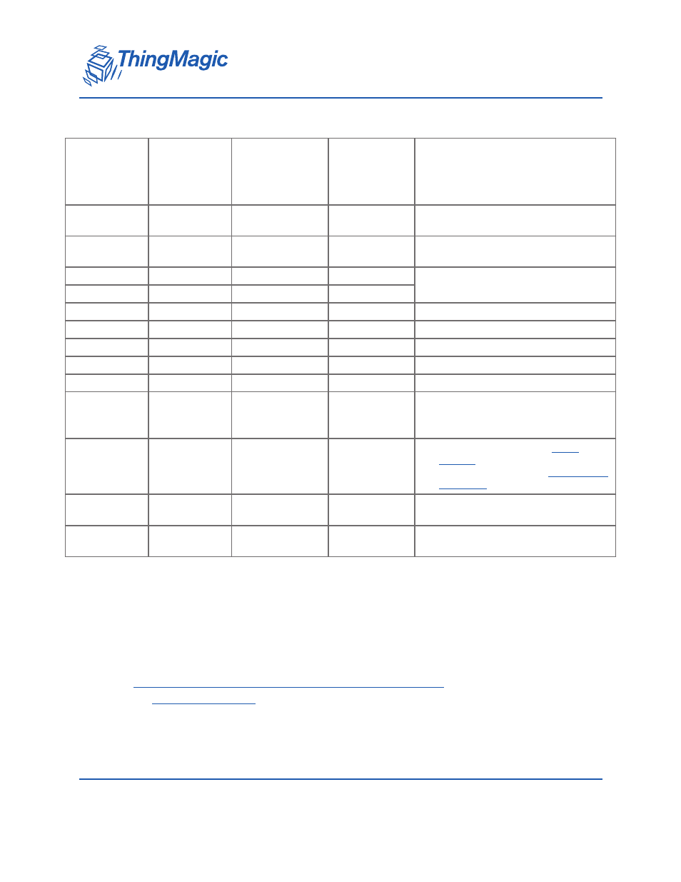
Micro Digital Connector Signal Definition
Edge Via
Pin #
Molex
53748-0208
Pin #
Signal
Signal
Direction
(In/Out of
Micro)
Notes
1-15, 21, 23,
29, 31
5-8
GND
P/S Return
Must connect all GND pins to ground
25, 27
1-4
Vin
P/S Input
3.5 to 5.25VDC. Must connect all Vin
supplies.
22
11
GPIO1
Bi-directional
Input 5VDC tolerant, 16mA Source/
Sink
24
13
GPIO2
Bi-directional
28
15
UART_RX_TTL
In
26
17
UART_TX_TTL
Out
18
14
USB_DM
Bi-directional
USB Data (D-) signal
16
12
USB_DP
Bi-directional
USB Data (D+) signal
20
9
USB_5VSENSE
In
Input 5V to tell module to talk on USB
19
19
SHUTDOWN
In
• HIGH or Open Circuit to ENABLE
module
• LOW or Ground to SHUTDOWN
17
20
RESET
Bi-directional
• HIGH output indicates
is running
30
U.FL
Antenna 1
Bi-directional
U.FL connector closest to the Molex
connector
32
U.FL
Antenna 2
Bi-directional
U.FL connector closest to the mod-
ule’s edge