Thingmagic, a division of trimble, M6e-micro module integration – ThingMagic Micro Hardware User Manual
Page 38
This drawing contains information that
is proprietary and confidential to
ThingMagic, Inc, and should not be
used without written permission.
ThingMagic, A Division of Trimble
Four Cambridge Center, 12
th
Floor, Cambridge, MA 02142 866-833-4069
M6e-Micro Module Integration
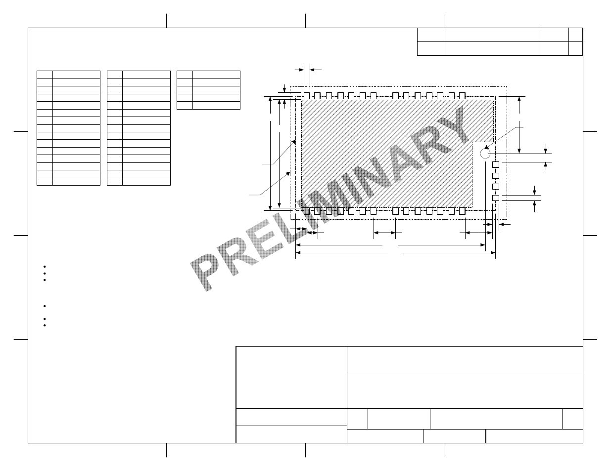
SMT Mounting Option
SIZE
DWG NO
REV
A
850-0005-01
X8
SCALE
2:1
SHEET
1 OF 5
REV.
DESCRIPTION
DATE
BY
DRAWN BY
R. Herold
DATE
4/9/12
Component
Keepout
D
C
B
A
4
3
2
1
D
C
B
A
4
3
2
1
0.980
No traces on top side in this area
32
31
30
29
Pin
1
3
5
7
9
11
13
15
17
19
21
23
25
27
Function
Gnd
Gnd
Gnd
Gnd
Gnd
Gnd
Gnd
Gnd
Ext Reset
Shutdown
Gnd
Gnd
Vin
Vin
Pin
2
4
6
8
10
12
14
16
18
20
22
24
26
28
Function
Gnd
Gnd
Gnd
Gnd
Gnd
Gnd
Gnd
USB DP
USB DM
USB 5VSense
GPIO1
GPIO2
RS232 TX
RS232 RX
0.050 typ
0.060 typ
0.100 typ
0.200
Module Outline
1
3
5
7
9
11
13
15
17
19
21
23
25
27
2
4
6
8
10
12
14
16
18
20
22
24
26
28
0.245
Pin
29
30
31
32
Function
Gnd
Antenna 1
Gnd
Antenna 2
All GND pads should be connected to a top layer copper
pour with no thermal reliefs.
GND clearance around antenna ports (pin 30, 32) should
be a minimum of 15mils to reduce capacitance. If the
U.FL connector is used for the antenna connection, pads
30 and 32 should be omitted.
0.050 typ
0.060 typ
Ensure that the antenna line impedance is 50Ω
Keep the antenna line on the PCB as short as possible
Antenna line must have uniform characteristics, constant cross
section, avoid meanders and abrupt curves. Matching elements (L
or C) can be added, but are not necessary for a well designed
layout.
Keep, if possible, one layer of the PCB used only for the ground
plane
Place EM noisy devices as far as possible from the M6e-Micro
Keep the antenna line far away from the power supply lines,
noisy devices such as fast switching ICs. If a switching power
supply is used, ensure that the switching frequency is 500kHz or
higher.
Optional 0.110"D
Mounting Hole
1.030
1.800
0.100
0.515
1.708
0.075
Reflow Solder MUST Be Performed With Shield Can Facing UP
ONE Reflow Cycle Maximum
01
Initial Release
RH
See Sheet 2 of this document for SMT reflow
profile recommendations.