Tjernlund SS1R SideShot (Discontinued) with UC1 Universal Control (Version X.04) 8504117 Rev 02/04 User Manual
Page 9
8
2. Using 1/2" bit, drill pilot holes noted on each side of the template from inside through rim-joist, wall board, siding, etc., keeping
drill bit perpendicular to the wall. 1/2" bit must be long enough to penetrate through exterior.
3. Remove template from rim-joist and attach to building exterior, aligning pilot hole markings on template with holes previously
created in Step #2.
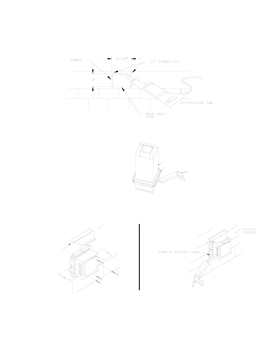
4. Drill the four corner holes noted on the template through the building exterior. Remove the template and mark lines from the
outside edge of the holes drilled, forming a rectangle.
5. Using reciprocating saw and appropriate blade, cut a rectangular opening through the rim joist, wall board, siding, etc., on the
lines marked in step 4. The rectangular opening should be no larger than 8-3/8" in width by 8" in height, (See Diagram C).
6. Knock out block material exposing rectangular opening through the wall.
7. Apply two beads of exterior rated caulk approximately 3/8" in width at the seam of the outermost casing of the Vent Hood and
the inner flange of the Vent Hood Terminus, (See Diagram D).
8. Slide the Vent Hood through the wall while taking care installing the rain shield as shown, (See Diagram E). The nuts located on
the Vent Hood outermost casing should be facing up when sliding it through the wall. Mount Vent Hood to the exterior using
four #8 x 3" wood screws and spacers provided, (See Diagram E). Wall anchors are provided for installation into masonry wall.
9. Connect the Plenum to the Vent Hood of the SS1-R following the steps on pages 9, 10.
10. After the SS1-R is completely installed, apply a bead of exterior rated caulk between the Vent Hood Terminus inner
flange and the exterior of the building, (See Diagram F).
DIAGRAM C
OUTERMOST CASING
DIAGRAM D
INNER FLANGE OF VENT
DIAGRAM E
RAINSHIELD
(INSTALL BETWEEN BUILDING
EXTERIOR AND INNER FLANGE
BUILDING
EXTERIOR
DIAGRAM F