Diagram r – Tjernlund SS1R SideShot (Discontinued) with UC1 Universal Control (Version X.04) 8504117 Rev 02/04 User Manual
Page 14
13
existing wiring and components are not damaged. The four wires connecting the Rheem, Ruud or Weatherking oil fired furnace to
the SS1-R must be routed through this hole to the burner junction box. If electrical conduit is not going to be used, then a mechan-
ical strain relief must be used where wires pass into the burner junction box.
For "D" series oil furnaces (-OBD-XXX, -OPD-XXX and etc.), remove the primary control from the main junction box and push
the wires inside to the side so that the holes on the back of the junction box can be seen. Once these holes are located, chose
one of these holes and trace its pattern onto the furnace wall. Once the hole is traced, remove the main junction box/primary
control assembly from the wall of the furnace and drill out the newly traced hole with a 1" drill. When the hole is complete,
install a 1" diameter bushing. If electrical conduit is not going to be used, then a mechanical strain relief must be used where
wires pass through the furnace wall. Replace the junction box / primary control to the wall of the furnace in the same fashion as
the original factory wiring.
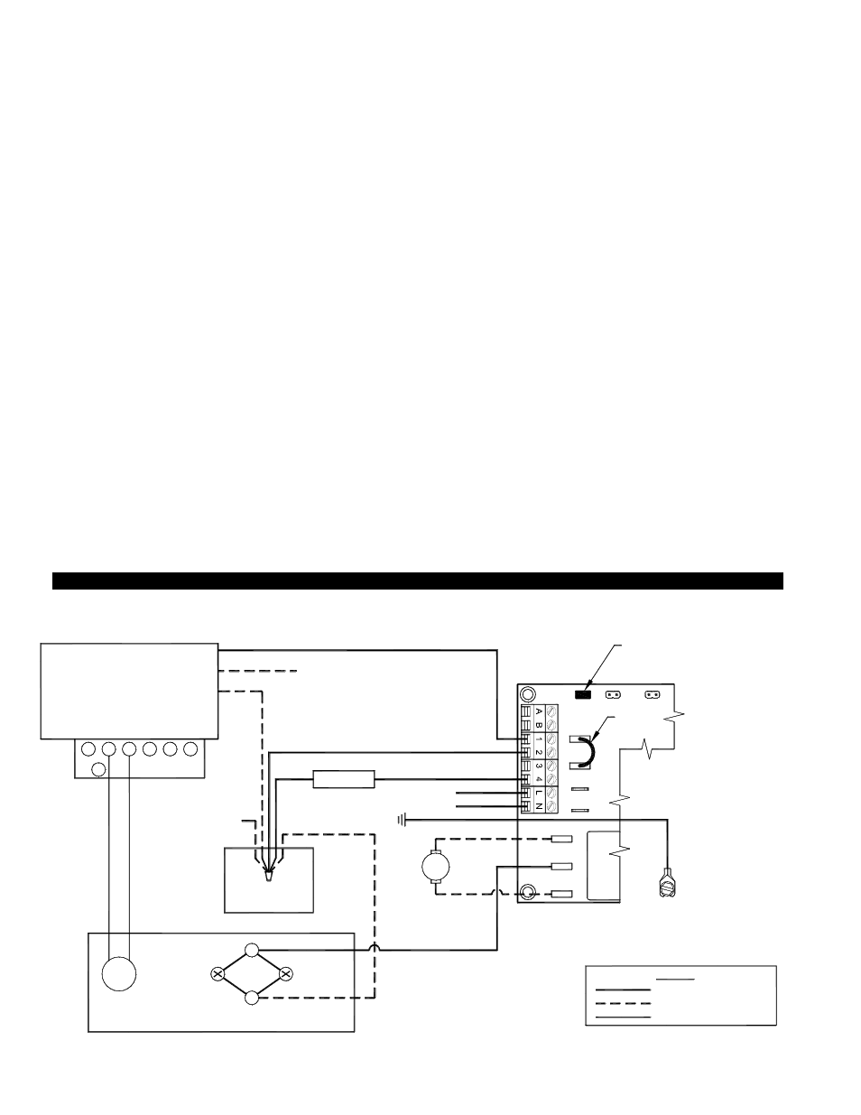
5. Remove the wire-nuts which secure the Orange to Black wires (burner control) and White wires (line neutral) of the primary
control, (see Diagram R below).
6. For "C" series oil furnaces (-OBC-XXX, -OPC-XXX & etc.), remove a knock-out slug from the existing junction box mounted to
the burner. A field installed bushing must be installed in the hole formed by removing the slug.
7. Use a field-installed wire and wire-nut to connect the Orange wire of the primary control to the #1 terminal on the SS1-R control
board, (see Diagram R below). All wire connections using wire nuts should be hidden in the junction box. Do not make wire
connections outside the junction box.
8. Use a field-installed wire and wire-nut to connect the White wire of the primary control to the oil valve and the #2 terminal on the
SS1-R control board, (See Diagram R below). All wire connections using wire nuts should be hidden in the junction box. Do
not make wire connections outside the junction box. Note: For "D" series oil furnaces (-OBD-XXX, -OPD-XXX and etc.), the
existing wire nut (which connects all the line neutrals together) is full and a new wire cannot be added to it. A new wire-nut will
have to be installed and this will require that the neutral wire is cut and stripped.
9. Use a field-installed wire from the #4 terminal of the SS1-R control board to the oil valve, (See Diagram R below). Note that the
other terminal on the oil valve is connected to line neutral in step 8 above.
10. Use a field-installed wire and wire-nut to connect the Black wire of the Beckett burner to the "M" terminal on the SS1-R control
board. All wire connections using wire nuts should be hidden in the junction box. Do not make wire connections outside the
junction box.
11. Connect the ground terminal of the SS1-R to the ground terminal of the burner junction box ("C" series oil furnaces), the
ground terminal of the main junction box, or some other suitable ground connection.
12. Connect 115VAC power to the "L" (line) and "N" (neutral) terminals of the SS1-R control board. This power should be routed
through a disconnect so that power to the SS1-R can be turned off remotely if necessary.
SS1-R WITH INTEGRAL UC1 UNIVERSAL CONTROL WIRED WITH RHEEM, RUUD OR WEATHERKING OIL FIRED FURNACES
50/60 Hz
SUPPLY
115 VAC
SPADE TERMINAL IN ELECTRICAL BOX.
GROUND
CRIMP GROUND WIRE TO GROUNDING
IMPORTANT:
C
F
F
R
W
G
Y
WHITE
BLACK
ORANGE
BECKET BURNER
TO BURNER
MOTOR
BLACK
B / W
TO FUSE
DISCONNECT
YELLOW
YELLOW
NEUTRAL
JUNCTION BOX
TO FACTORY-WIRED
LIMIT SWITCHES
VIA JUNCTION BOX
GROUNDED
LEGEND:
LOW VOLTAGE
115 VAC, FIELD-WIRED
115 VAC, FACTORY-WIRED
VENTER MOTOR
(FACTORY-WIRED)
SENSOR
TO IGNITION
TRANSFMR
OIL VALVE
IMPORTANT:
XL
J1
J2
115V
DRY
24V
D/N 9183047-5
CALL
JUMPER
PRIMARY CONTROL
y
RED JUMPER POSITION MUST BE THE SAME
AS APPLIANCE INTERLOCK VOLTAGE.
UNIV
E
R
S
A
L CO
NT
RO
L
XN
TO FLAME
NM
T
R
M
DIAGRAM R