Tjernlund SS1R SideShot (Discontinued) with UC1 Universal Control (Version X.04) 8504117 Rev 02/04 User Manual
Page 15
SEQUENCE OF OPERATIONS WITH SS1-R POWER SIDEWALL VENTER INSTALLED ON
RHEEM, RUUD, OR WEATHERKING OIL-FIRED FURNACES.
When the thermostat calls for heat, the circuit across the T-T terminals on the Honeywell 8184 series burner control is closed.
This causes 115 VAC to be applied to the Orange wire that exits the bottom of the Honeywell primary control. This Orange wire
applies power to terminal #1 of the SS1-R integral UC1 Universal Control board. The #1 contact on the terminal strip supplies 115
VAC to the "M" and "MTR" spade connections on the SS1-R control board causing the Beckett burner and the induced draft motor
to start immediately upon a thermostat heat-call. At this point, the burner is running, but the oil valve is still off, so combustion has
not yet started. When the induced draft motor gets enough speed to close the pressure switch, the switch contacts operate a relay
on the control board which then supplies power to terminal #4 of the SS1-R control board, turning on the oil valve. At this point,
combustion should take place.
Once the thermostat is satisfied, the Honeywell 8184 burner control will remove 115 VAC power from the Orange wire exiting its
base. As a result, the oil solenoid valve snaps closed immediately and this action causes the burner flame to extinguish immedi-
ately. The loss of power to terminal #1 of the SS1-R integral UC1 Universal Control board begins the post-purge period. The "M"
and "MTR" terminals on the SS1-R control board will remain energized with 115 VAC for the entire post-purge period. This means
that both the Beckett burner and the Induced draft motor of the SS1-R will remain powered for the user-selected post purge period
(although no flame is present). No flame will be present during the post-purge period because the oil solenoid (which was turned
off immediately when the heat-call ended) will prevent the oil from flowing.
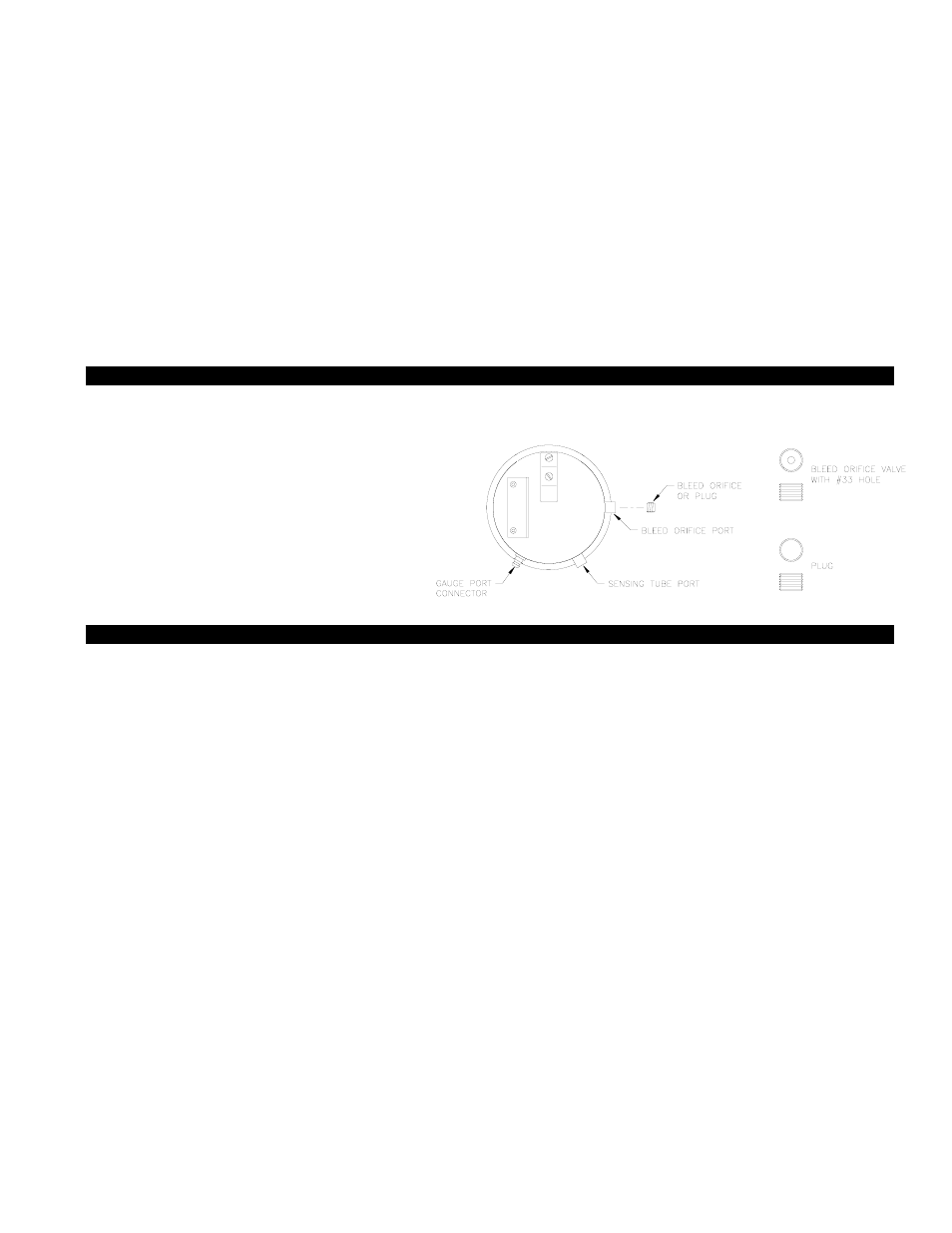
SELECTION OF PRESSURE SWITCH BLEED ORIFICE
In order for the SS1-R pressure switch to function properly for the intended application, the proper bleed orifice has to be selected
as determined below.
1. Upon installation, if the furnace input rate is 1 gallon
per hour or less (140,000 BTU/hr. or less), then the
plug should be installed in the pressure switch.
2. Upon installation, if the furnace input rate is greater
than 1 gallon per hour or 140,000 BTU/hr., then the
#33 bleed orifice should be used.
3. Once the proper bleed orifice has been determined,
install into bleed orifice port as shown in Diagram S.
DRAFT ADJUSTMENT OIL
The SS1-R Vent system will properly vent a wide range of BTU/hr. input capacities. To compensate for different burner capacities,
vent connector lengths and wind conditions it features a draft adjustment located on the outside of the Vent Hood. In general,
positioning the draft adjustment inward will cause the SS1-R to operate at lowest capacity. Positioning the draft adjustment
outward will cause the SS1-R to operate at highest capacity.
IMPORTANT:
The following paragraph describes the initial draft adjustment. It may be necessary to make a slight readjustment to compensate
for various conditions: wind, vent connector resistance, negative building pressure and multiple appliances.
ASHRAE lists the average design factor for wind loads in North America at 15 MPH. Refer to the Draft Adjustment Chart below.
We recommend that the 25 MPH category be used to allow for excursions beyond the 15 MPH average. It is not recommended
for the SS1-R to be terminated on a wall that faces the direction of the prevailing winds. Backdrafts by severe winds can cause oil
odors to remain in the structure and/or interrupt heating equipment operation. If the SS1-R is terminated in a direction prone to
higher winds, or if higher winds are common in your geographic area, use the 40 MPH category to determine the proper draft
adjustment setting. If the draft adjustment is set at the 25 MPH category and sustained winds exceeding 25 MPH are present, the
Fan Proving Switch will act to close the oil solenoid valve. Wind loads referenced are based on straight line winds directed against
the Vent Hood.
DRAFT ADJUSTMENT PROCEDURE:
1) Set the draft adjustment to the appropriate setting based on the above instructions and the Draft Adjustment Chart. Adjustment
is accomplished by loosening both nuts on each side of the Vent Hood and centering both indicators to the desired setting.
Tighten the four nuts to secure the draft adjustment at desired setting.
2) Place the appliance and SS1-R in operation. Measure the over-fire draft. Make necessary adjustments to the primary
air intake and barometric draft control to comply with the over-fire draft requirements of the appliance. The over-fire draft
should be in a range of -.02" to -.04" W.C., with the optimum setting at -.03” W.C. If adjustments to the primary air intake and
barometric draft control do not provide the required over-fire draft, the SS1-R draft adjustment must be repositioned, accord-
ingly. Measure over-fire draft after repositioning SS1-R draft adjustment.
14
DIAGRAM S