Tjernlund SS1R SideShot (Discontinued) with UC1 Universal Control (Version X.04) 8504117 Rev 02/04 User Manual
Page 11
10
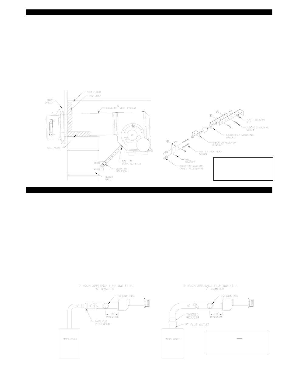
INSTALLATION OF WALL SUPPORT BRACKET
1. To prevent damage to the SS1-R, temporarily support the bottom of the plenum (prop on ladder) while assembling the wall
support bracket. Assemble the wall support bracket as shown, (See Diagram J).
2. Using the prepunched holes, adjust the wall support bracket so that a slight pitch is maintained for water drainage, (See
Diagram J).
3. Use the prepunched holes on the wall bracket as a template to mark holes to be drilled into the side wall for mounting screws.
4. a)
If installing the bracket into a wood wall, drill 2 pilot holes at each point established in step 3 with a 1/8" drill bit
approximately 1" deep and install the screws provided to secure the bracket to the wall.
b)
If installing the bracket into a masonry wall, drill 2 holes at each point established in step 3 with a 1/4" masonry drill bit
approximately 1" deep. Tap the masonry anchors into the holes drilled in step 4. Screw the wall bracket onto the wall.
5. Connect the other end of wall support bracket to the stud on the plenum using the supplied 1/4"-20 keps nut, (See Diagram J).
INSTALLATION OF VENT PIPE
Single wall vent pipe is not allowed in unconditioned or unheated space. When Installing the SS1-R vent system, a barometric
draft damper control must be used. Install the barometric draft damper as close as is practical to the SS1-R with the center line of
the barometric damper not closer than 10 inches to the SS1-R inlet. Always install the draft damper in a 6” section of pipe. The
general venting configurations are shown in diagram K. The SS1-R vent system is designed to accept 6” single wall, type”L” or
type “A” vent pipe. When installing the vent system, it will be necessary to use the tapered reducers or increasers as shown.
Determine which inlet of the SS1-R will allow for the least amount of elbows to the furnace. When using single wall pipe, a mini-
mum clearance of 18” must be maintained between the vent pipe and combustible materials and the vent pipe must be exposed to
view for its entire length. If this clearance cannot be maintained, type “L” or type “A” vent may be used according to its listing and
vent pipe manufacturers instructions.
A maximum of 10 linear feet of vent may be used to connect the SS1-R to the furnace. No more than three 90
0
elbows may be
used (two 45
0
elbows will be considered equivalent to one 90
0
elbow).
The SS1-R vent system is shipped from the factory with the plug connected to the rear and the vent pipe inlet collar connected at
the bottom. If using the bottom inlet, read the section entitled “Vent Pipe Clamp Assembly”, page 11. If the installation requires
the use of the rear inlet, follow the steps in the section entitled “Vent Pipe Inlet Collar Conversation”, page 11 to move the vent
pipe inlet collar from the bottom to the rear.
DIAGRAM J
DIAGRAM K
IMPORTANT:
Adjust SS1-R mounting
bracket for a slight downward
pitch towards exit terminal.
IMPORTANT: Oil installations
must have a barometric draft
control.