Tjernlund SS1R SideShot (Discontinued) with UC1 Universal Control (Version X.04) 8504117 Rev 02/04 User Manual
Page 5
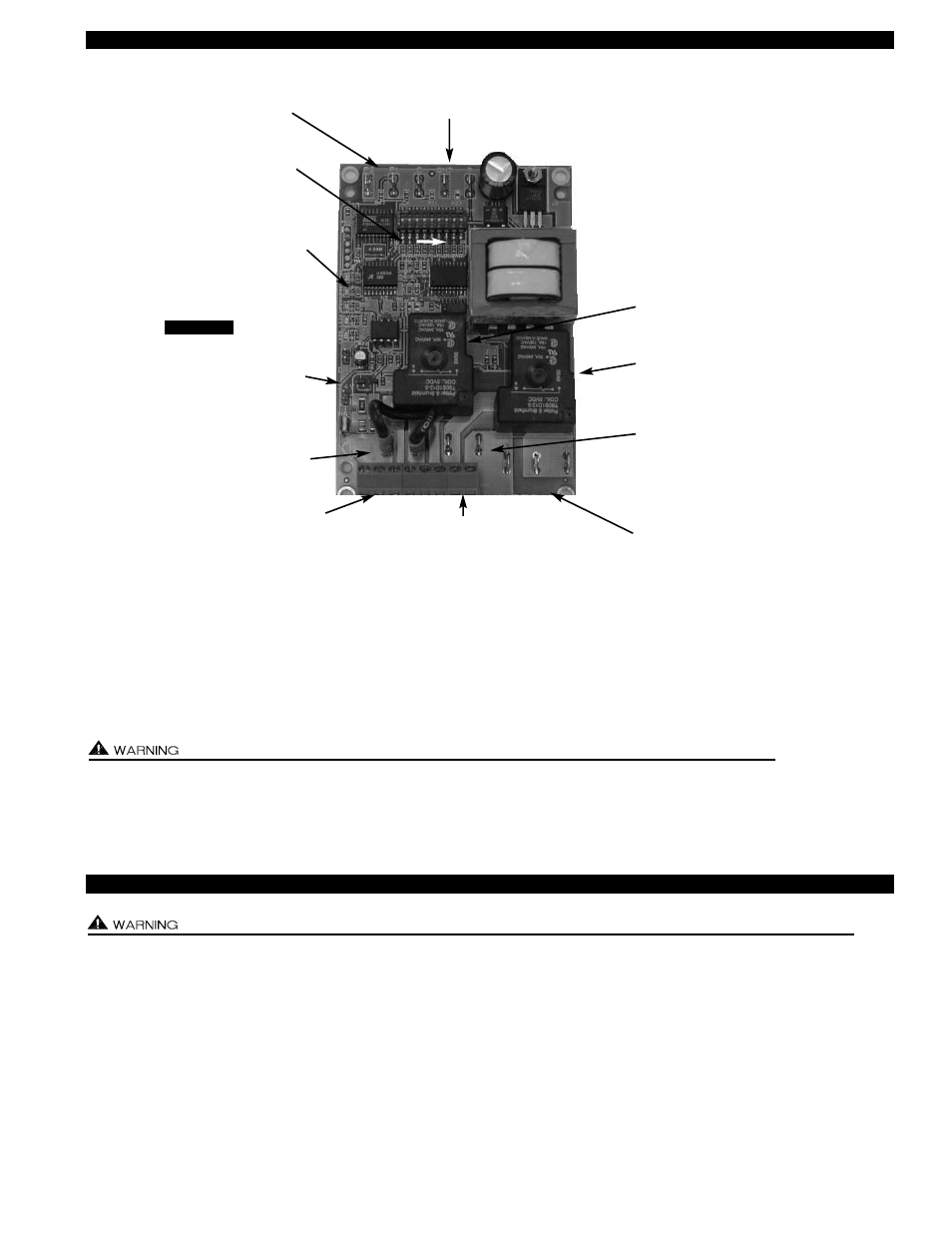
SS1-R WITH INTEGRAL UC1 UNIVERSAL CONTROL BOARD FEATURES
# 1.
Power supplied by board. Do not supply power to this area or control damage may result.
# 2. Do not supply power to the appliance interlock block with the call selector in the “DRY” position.
Control damage may result if power is supplied.
# 3. Circuit protection must be provided by the installer. 16 Amps is the maximum current allowed for this device at terminal L.
VETI
A 15 Amp circuit breaker is recommended.
VETI
I
A
PRE / POST PURGE AND PROVER STATUS CHECK DIP SWITCH SETTINGS
Remove power to SS1-R and heating equipment when installing, servicing or changing dip switch settings. Failure to do so may result in
personal injury and/or equipment damage. LED #5 (RED) should not be on if 115 VAC supply power is removed from the control.
Pre-purge
Used for longer vent runs to get draft fully established throughout the vent system prior to burner ignition. Also beneficial for nega-
tive pressure prone environments. IMPORTANT: Nuisance equipment lockouts may occur if our pre-purge is running in conjunc-
tion with and is longer than any equipment timing circuit. Pre-purge settings must be shorter than burner control lockout time
unless wired prior to burner control timing circuit (i.e. aquastat / thermostat).
Post-purge
A Venter post-purge has been factory set at 2 minutes. Confirm that dip switch #5 is in the up or "on" position. Oil fired equipment
requires that the post-purge be long enough to eliminate post cycle nozzle drip odor. A longer post-purge may be necessary for
longer vent runs or high heat retention, refractory lined combustion chambers.
4
LED 1 (AMBER)
LED 2 (GREEN)
LED 3 (GREEN)
LED 4 (RED)
LED 5 (RED)
DRY
24 V
115 V
APPLIANCE
INTERLOCK
RELAY
VENTER
MOTOR
RELAY
A B 1 2 3 4 L N
J1 J2 XL XN
P1 P2 C GND F
(1 9)
N M MTR
XL / XN AUXILIARY DEVICE
POWER TERMINALS
115 VAC - Maximum of 0.15 Amps.
Only connect to Tjernlund auxiliary devices.
SEE WARNING # 1.
LED STATUS LIGHTS
See “LED Status & Fault
Indicator Section” for details.
J1- J2 CALL
JUMPER
Used when the call signal is
used as the “proven” return
signal to the appliance. See
wiring section for details.
APPLIANCE INTERLOCK
TERMINAL BLOCK (A-B, 1-4)
A - B - Dry Contact call. 3 mA @ 5VDC.
SEE WARNING # 1.
1 - 24 or 115 VAC intercepted call.
IMPORTANT: RED voltage jumper must
match intercepted call voltage.
2 - 24V common or 115V Neutral.
3 - Common terminal to appliance relay con-
tacts. IMPORTANT: J1-J2 jumper routes
call voltage at terminal 1 to 3. Remove
J1-J2 jumper if a different voltage source is
provided to terminal 3.
4 - Normally open terminal of appliance relay.
Will be energized from terminal 3 if safety
circuit is “proven”.
L / N - 115 VAC POWER
SUPPLY BLOCK
115 VAC / 50-60 Hz
Circuit protection provided by installer.
SEE WARNING # 3.
MTR & M LOAD TERMINALS
FROM VENTER MOTOR RELAY
Used to drive SS1-R Motor & Burner Motor.
1 HP MAX LOAD across terminals MTR & M / N.
APPLIANCE INTERLOCK
RELAY
1 HP MAX LOAD across
terminals 3 & 4.
VENTER MOTOR RELAY
1 HP MAX LOAD from
terminals L to MTR & M.
P1 - P2 SAFETY CIRCUIT
TERMINALS
1 mA @ 5VDC.
SEE WARNING # 1.
C, GND, F AUXILIARY DEVICE
COMMUNICATION TERMINALS
2 mA @ 5VDC. For Tjernlund MAC1E or
MAC4E auxiliary devices. SEE WARNING # 1.
APPLIANCE CALL
VOLTAGE SELECTION
Place RED voltage jumper in
proper location based on
appliance call interlock volt-
age. SEE WARNING # 2.
IMPORTANT
DIP SWITCH SETTINGS
Pre-Purge (1-2)
Post-Purge (3-8)
Prover status check (9)
See “Pre / Post Purge &
Prover Status Check Dip
Switch Settings”.