Fig. e – Thetford 19613 - Mechanism Assembly User Manual
Page 2
Mechanism Assembly
Part #19613
Page 2
8. Remove Blade Seal from white mechanism plate. Discard.
9.
Important: If your mechanism plate has two holes at front (dotted lines in
Fig. D), AND no leakage is suspected at foam gasket area, you do not need
to install the new plate provided in this kit. Skip down to the heading “To
Replace Mechanism.”
To remove Mechanism Plate, loosen the 3 Screws in well nuts (WN,
Fig. D) and pull the plate off the bowl. If well-nuts do not come out with
the plate screws, either push them through to the interior or re-insert the
screws to pull them out. Discard plate and well-nut hardware.
10. Scrape off old Seal from china with sharp tool. Use mineral spirits or
alcohol to remove residue.
To Replace Mechanism Plate
(if it has been removed)
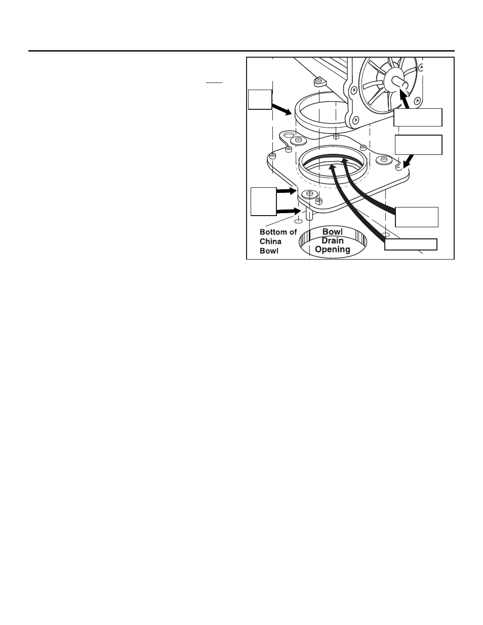
1. Apply a 1/4” wide continuous ring of caulk sealant around the top of the
exposed side of the flat foam seal. (Fig. E).
2. Line up well-nut assemblies on the mechanism plate with the holes in
the china bowl. Then line up the openings and press into place.
Lightly
hand-tighten the well-nuts to temporarily secure its position.
To Replace Mechanism
1. Wet blade seal with clean water.
2. Fully seat new blade seal, lip up, onto Mechanism Plate (Fig. E).
3. To avoid damaging blade seal, make sure blade in new mechanism is
fully closed. Turn mechanism lead screw counter-clockwise to close
valve (Fig. E).
4. Connect 2 Motor Leads, yellow-yellow, green-green (Fig. A).
5. Working from the back, position Mechanism in Toilet. NOTE: on some
low-profile units, it may be a tight squeeze. Align mechanism over
Mechanism Plate, press down and secure with four screws (MS, Fig.
D).
6. Turn toilet over to check centering. Loosen well-nuts to re-center if
needed.
Do the permanent tightening down of the well-nut screws
at this time by hand. Tighten in a diagonal pattern to get an even
seal. Be careful not to overtighten and cause deflection of the plate
at the edges. Wipe off excess sealant when done.
7.
If Overflow tube present (pre-3-16-03 Arias): Cut approximately 1” off
Overflow Tube. Remove silicone cap from Mechanism. Forming a full
loop, reattach to Mechanism. Tuck in and away from lead screw.
If Overflow tube not present: Leave silicone cap on Mechanism;
proceed to next step.
8. If you removed the Controller Assembly and/or the Switch Box, re-install
now, using the adhesive foam pads provided. If you removed Metal
Bracket, reinstall.
9.
High Profile: To install Extension Tube (Refer to Fig. C):
a. Lubricate sealing surface of Extension Tube Seal with silicone
grease.
b. Install Extension Tube Seal on Extension Tube.
c. Install Extension Tube and seal assembly on Mechanism. Make sure
that seal is seated at least 1/2 inch below Mechanism tube lip.
d. Ensure Hose Clamp on Mounting Flange Seal is tight.
e. Lubricate Mounting Flange Seal sealing surface with Silicone
Grease.
f. Install Mounting Flange and Seal assembly on Extension Tube. Make
sure there is at least a 1/2” overlap between the Extension Tube
and Mounting Flange Seal.
Low Profile: Replace the Mounting Flange Seal onto the lip of the
Mounting Flange. Install Mounting Flange to Mechanism. (No exten-
sion tube is used.)
10. Replace 2 Mounting Bushings with flat surface out.
To Test Mechanism Operation
1. Connect toilet to RV’s 12V DC power.
2. Turn on 12V DC to toilet at RV power distribution panel.
3. Press the Flush button on Key Pad and observe mechanism operation.
The solenoid valves will click on and off during the flush cycle.
4. Press both Key Pad buttons, twice, to open blade.
To Replace Toilet To Floor
1. Secure new Closet Flange Seal, lip side up, to Toilet.
2. Set Toilet close enough to hook up water supply.
3. Reconnect Water Supply Line.
4. Turn on water and check for leaks at the water connection. Correct any
leakage.
5. Position Toilet over flange. Arrange wiring clear of Mechanism Lead
Screw (Fig. E) and base of toilet.
6. Secure to floor with Lag Screws. Tighten.
7. Press Toilet flush button controls to add water and to flush test. Check
for leaks.
8. Resecure Bolt Caps.
Flat Foam
Seal
Mechanism
Lead Screw
Blade
Seal
Mechanism
Plate
Caulk Sealant
Fig. E
Well-nut
ass’y