2 assembly procedure – Rice Lake TradeRoute HL Series - Operation Manual (Legal-for-Trade) User Manual
Page 29
Maintenance
25
4.3.2 Assembly Procedure
1. Install the new bushings into the lift arms using Loctite 603
™
. This product will
retain the bushings and resist mild oil contamination.
2. Insert lower load cell pin (21) into lift plate (23).
3. Insert roll pin (22) to hold the pin in place with roll pin punch and hammer.
4. Assemble inner lift arm (4) onto pivot pin on base (1).
5. Assemble hydraulic cylinder onto lower cylinder pin on base (1).
6. Insert upper cylinder pin (8) through cylinder (2) into the inner lift arm (4).
7. Assemble load cell assembly (19 and 20) onto lower load cell pin (21).
8. Apply a thin film of grease onto ends of upper load cell pin (18).
9. Insert upper load cell pin (18) through upper eyebolt (20) into inner lift arm (4).
10. Assemble outer lift arm (5) loosely onto the three pins (pivot, upper load cell, and
upper cylinder).
11. Place lift arm spacer (9) between two lift arm plates and press outer lift arm fully
onto the pins.
12. Insert cap screw (10, 11) and start threads – do not tighten – with 3/4" allen
wrench.
13. Insert pivot bolt (13), washer (15), and lock washer (14) into pivot pin and tighten
with 3/4" wrench.
14. Tighten cap screw (10, 11) with 3/4" allen wrench.
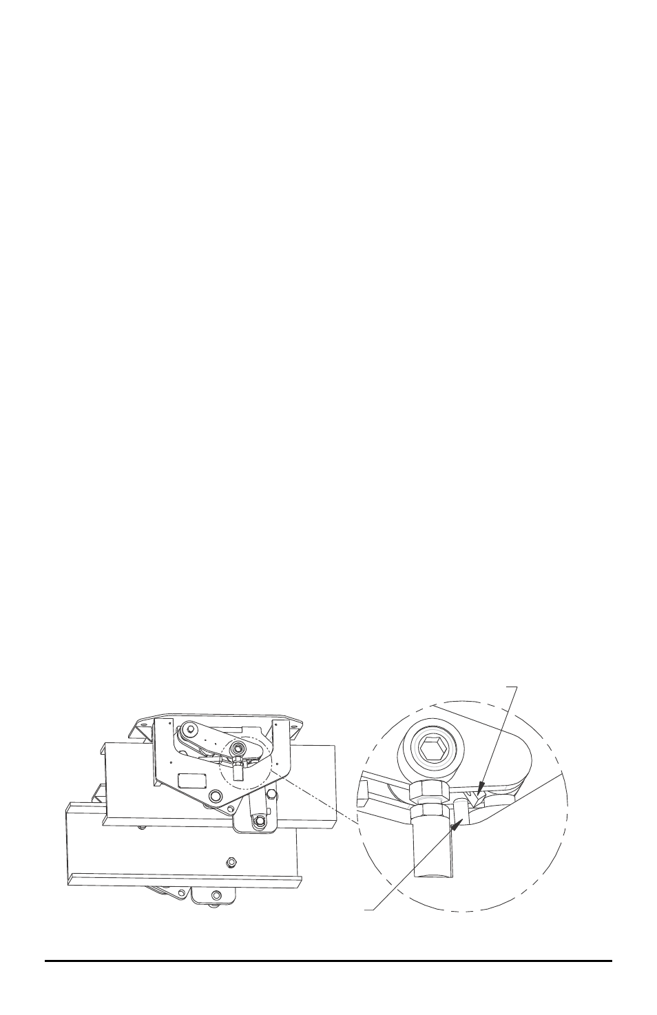
15. Turn out the lockdown bolt (24) until cylinder is extended between 1/8" and 1/4"
with 3/4" wrench. Tighten the jam nut (25).
16. Insert roll pin (22) through the lower load cell pin (21) to prevent the load cell
assembly from jumping off the pin with roll pin punch and hammer.
17. Insert retaining ring (3) on lower cylinder pin.
18. Assemble hydraulic fittings (56, 57) if required with 11/16" and 5/8" wrenches.
19. Attach load cell cover (26) with 1oad cell cover bolts (27) and lock washers (28)
with 7/16" wrench.
Figure 4-3 Reed Switch Location
Reed Switch Magnet
Reed Switch