Rice Lake TradeRoute HL Series - Low Profile Installation and Setup for Models from 2011 and Older 128406 User Manual
Page 40
37
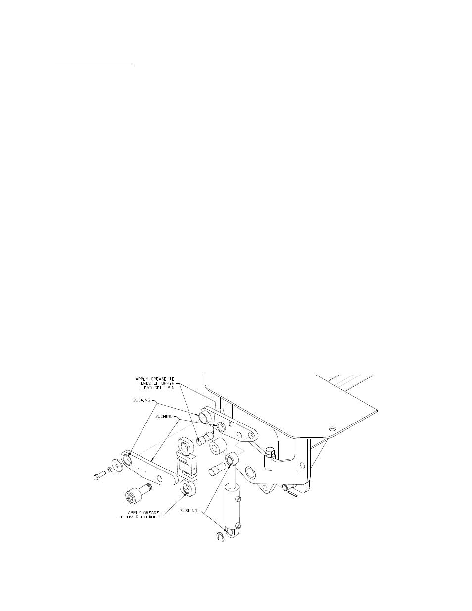
Assembly Procedure (refer to parts drawings pages 37 and 38)
1. Insert lower load cell pin (34) into lift plate (36 or 43) insert roll pin to hold the pin in place
with roll pin punch and hammer.
2. Assemble inner lift arm (4 or 6) onto pivot pin on base (35 or 42).
3. Assemble hydraulic cylinder (1) onto lower cylinder pin on base (35 or 42).
4. Insert upper cylinder pin (8) through cylinder (1) into inner lift arm (4 or 6).
5. Assemble load cell assembly (32,33) onto lower load cell pin (34).
6. Apply a thin film of grease onto ends of upper load cell pin (31).
7. Insert upper load cell pin (31) through upper eyebolt (33) into inner lift arm (4 or 6).
8. Assemble outer lift arm (5 or 7) loosely onto the three pins (pivot, upper load cell, and
upper cylinder).
9. Place lift arm spacer (9) between two lift arm plates and press outer lift arm fully onto the
pins.
10. Insert cap screw (10,11) and start threads, do not tighten, with 3/4” Allen key.
11. Insert pivot bolt (13), washer (15) and lock washer (14) into pivot pin and tighten with 3/4”
wrench.
12. Tighten cap screw (10,11) with 3/4” Allen key.
13. Turn out the lock down bolt (18) until cylinder is extended between 1/8” and 1/4” with
3/4” wrench. Tighten the jam nut (19).
14. Insert roll pin (17) through the lower load cell pin (34) to prevent the load cell assembly
from jumping off the pin with roll pin punch and hammer.
15. Insert retaining ring (3) on lower cylinder pin with a hammer.
16. Assemble hydraulic fittings (55,56,57), if required, with 11/16” and 5/8” wrenches.
17. Attach load cell cover (37 or 44) with 1oad cell cover bolts (20) and lock washers (21) with
7/16” wrench.