Table 2-1. junction box connections, Figure 2-3. junction box wiring diagram, Figure 2-4. load cell protection – Rice Lake Summit 3000 Low-Profile Package User Manual
Page 9: Check all strain relief fittings for tightness, Secure the summit 3000 floor plate
Installation
5
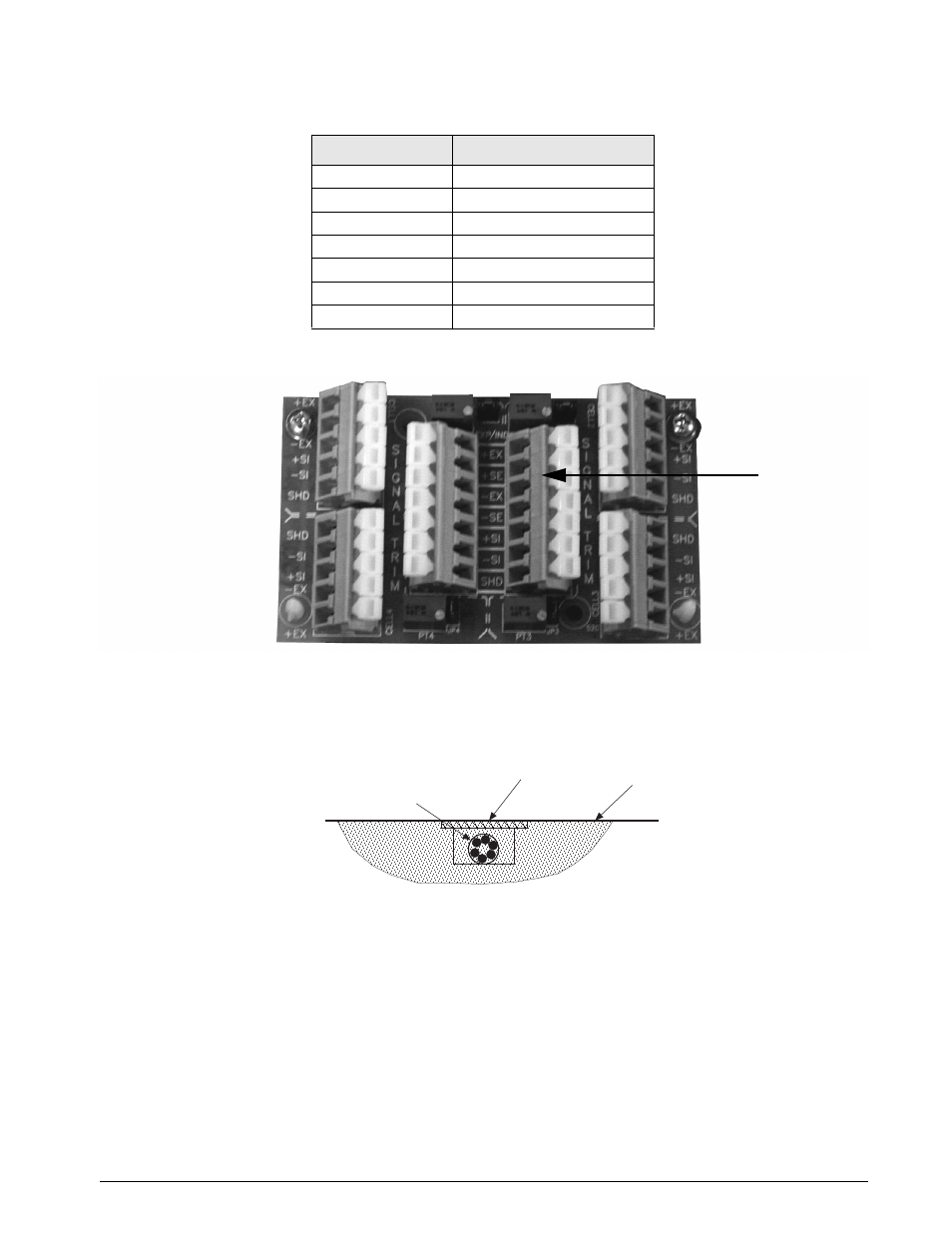
Figure 2-3. Junction Box Wiring Diagram
7. The cable must be routed to the indicator in a manner that will protect the cable from damage. This
method of cable protection in non-washdown applications are shown in Figure 2-4. When planning cable
routing, leave a loose coil of excess cable under the scale to facilitate future lifting of the scale for
servicing or cleaning.
Figure 2-4. Load Cell Protection
8. When the interface cable is protected and in its final position, complete connections to the indicator. See
the indicator installation manual for wiring information.
9. If necessary, trim corners as described in Section 3.2.
10. Check all strain relief fittings for tightness.
11. Put the cover back onto the junction box assembly and place the junction box back into the floor scale
cutout.
12. Secure the Summit 3000 floor plate.
Cable Color Code
Junction Box
Red
+ Excitation
Black
- Excitation
Green
+ Signal
White
- Signal
Bare
Shield
Yellow
+ Sense
Blue
- Sense
Table 2-1. Junction Box Connections
I n d i c a t o r
Te r m i n a l
Location
FLOOR
LOAD CELL CABLE
STEEL COVER