4 assembly, 1 installing and adjusting feet, 2 anchor plate installation – Rice Lake Summit 3000 Low-Profile Package User Manual
Page 8: Figure 2-2. anchor plate installation, 5 electrical interface to indicator, Remove the four screws using an allen wrench, Slide the junction box assembly out of the deck, Open and remove the top of junction box
4
Summit 3000 Installation Manual
Lift the scale only with a properly designed spreader bar as shown in Figure 2-1.
Lifting force must be vertical to avoid bending the eye bolts.
Eye bolts must always be inserted into the top of the scale. Lifting should always occur with
the top plate facing up and the eye bolts securely attached through the nuts welded to the
bottom side of the top plate. Lifting from the bottom of the plate could cause nuts to break
loose and the scale to fall.
2.4
Assembly
The following paragraphs give instructions for installing and adjusting the scale feet and anchor plate.
2.4.1
Installing and adjusting feet
For load cell protection during shipping, the scale feet are shipped separately from the floor scale.
Screw one foot into each load cell and turn all the way in until the foot touches either the load cell or the
underside of the deck. Then unscrew each foot three complete turns.
Place a spirit level on the deck. Adjust any “high” corners not in contact with the floor by further unscrewing the
feet on those corners until they just contact the floor surface. When all feet are in contact with the floor, check the
deck with the spirit level to be sure the scale is within 1/4 inch of level.
2.4.2
Anchor Plate Installation
For permanent applications, the scale should be secured to the floor to prevent sideways movement. Two mild
steel floor anchor plates, with holes that slightly exceed the foot diameter, are available as an option for that
purpose.
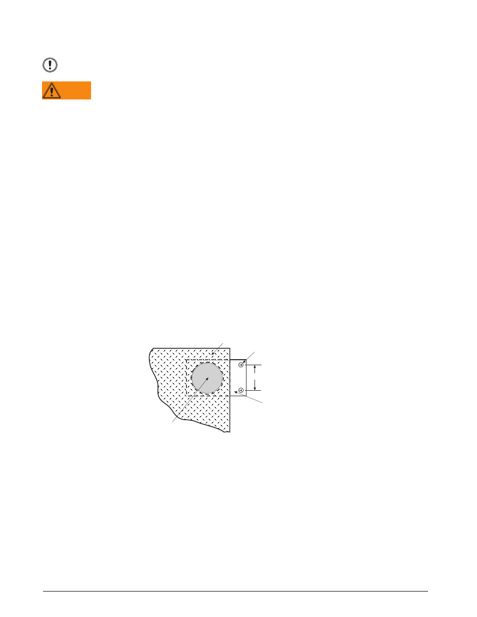
Lift the scale so that the feet are approximately one inch off the floor. Slide mounting plates under two diagonally
opposed feet. Lower the scale back to the floor, and position the plates as shown in Figure 2-2 so that the
boltdown holes are accessible from above.
Using the mounting plates as templates, drill pilot holes into the floor for suitable anchor bolts. Bolt the plates to
the floor using 1/2-in anchor bolts. Recheck foot adjustment and deck level after this operation.
Note: For installations using access ramps, mounting plates are not necessary as the ramps have built-in mounting plates to
secure the scale feet.
Figure 2-2. Anchor Plate Installation
2.5
Electrical Interface to Indicator
Twenty feet of 6-wire cable to connect the scale to the weight indicator is supplied with each scale. The junction
box is easily accessible through a top access plate located on the top of the Summit 3000. Use the following steps
to wire up the junction box.
1. Remove the four screws using an allen wrench.
2. Slide the junction box assembly out of the deck.
3. Open and remove the top of junction box.
4. Push the cable end into the junction box through a cord grip.
5. Connect the wires to the indicator terminal (Figure 2-3) as shown in Table 2-1.
6. Pull out excess and tighten the cord grip to hold the cable snugly.
Important
WARNING
3.50"
.56" DIA (2K–10K models)
ANCHOR PLATE
SCALE DECK
FOOT