Figure 4-1. load cell assembly, Figure 4-2. bottom view of scale – Rice Lake Summit 3000 Low-Profile Package User Manual
Page 15
Service Information
11
Lift the scale with a chain and remove foot, then remove the defective load cell. Disconnect load cell cable from
the junction box and cut cable ties. When the cable is freed, pull cable out of the scale frame channels.
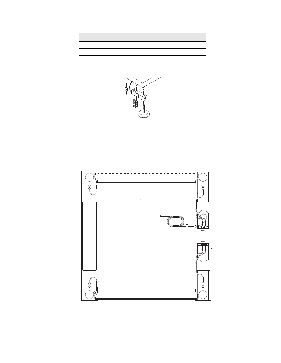
Figure 4-1. Load Cell Assembly
Follow the directions given below to install new load cells.
Lay out the four load cells near the corners where they are to be installed. Thread the cable from each load cell
through the conduit tubing in the frame and into the junction box according to the wiring diagram in Figure 4-2.
Note that in Figure 4-2 both the scale and the junction box are viewed from the bottom. To verify correct load
cell/junction box terminal matching, see the numbers on the terminals inside the junction box and the corner
numbering diagram in Figure 4-4 on page 12.
Figure 4-2. Bottom View of Scale
Check that the threaded holes for the load cell screws are free of debris. Use compressed air to blow out holes if
necessary. Position load cells with alignment arrows pointed up toward the deck and loosely install the hex head
cap screws provided, as shown in Figure 4-1. If the base is used with a pit frame or access ramp, position the load
cell to maintain the dimension shown in Figure 4-3. With the torque wrench, tighten all bolts to 75 ft-lbs.
30112
5K models
2500 lb (1134.0 kg)
30270
10K models
4000 lb (1814.4 kg)
Rice Lake PN
Summit Model #
Load Rating
Table 4-2. Load Cell Replacement Numbers
CELL 1
CELL 4
CELL 2
CELL 3