1 trimming procedure, Trimming procedure, Electrical interface to indicator – Rice Lake RoughDeck AX User Manual
Page 9: Figure 2-3. signal trim main board
Installation
31
Electrical Interface to Indicator
Twenty feet of 6-wire cable to connect the scale to the weight indicator is supplied with each scale. The cable must
be routed to the indicator in a manner that will protect the cable from damage. Two methods of cable protection in
non-washdown applications are shown in Figure 4. When planning cable routing with either of these two methods,
leave a loose coil of excess cable under the scale to facilitate future lifting of the scale for servicing or cleaning on
the indicator terminal using the same procedure as inserting load cell cables to the appropriate connectors.
Note
If cables could be exposed to water or other liquids, bend a short downward loop in all cables near the cord grips so
any fluids draining down the cables will drip off before reaching the junction box.
2.5.1
Trimming Procedure
Trimming is a process of equalizing the output from multiple individual load cells. If needed, load cell output can
be individually trimmed with potentiometers.
Whenever a substantial amount of trim (more than 5% of normal output), seems necessary to equalize output,
check for other possible problems. The best trim is always the least amount of trim. When all errors except cell
mismatch and cable extensions or reductions have been corrected, continue with the trimming.
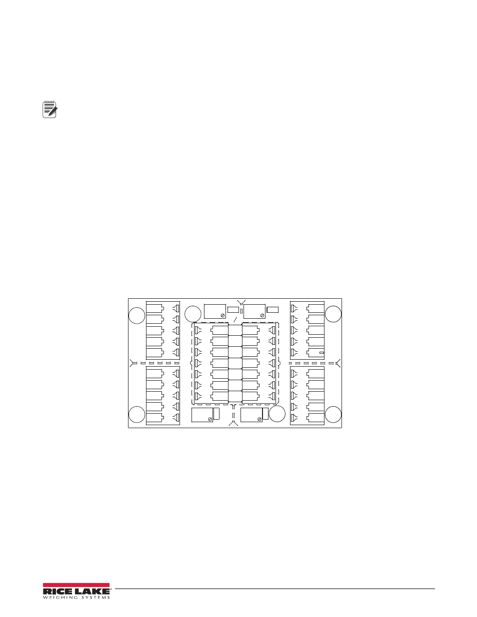
Use the following steps to properly trim the Tuffseal junction box.
1. Determine the number of load cells needed.
2. Make sure jumpers are in place to enable trimming of the cells corresponding to each load cell. See Figure
2-3 for the location of jumpers JP1, JP2, JP3, and JP4. Note that you need to remove jumpers for any
unused cells.
3. Set all potentiometers fully clockwise to give maximum signal output from each cell (cell below for
location of potentiometers).
JP4
JP 2
PT4
PT3
JP3
PT1
EXP
PT2
JP1
1
CELL4
1
CELL1
1
CELL3
1
CELL2
IND
-EX
-SI
SHD
+SI
+EX
M
R
N
I
-SI
S2 C
I
A
G
+EX
+SI
-SI
SHD
-EX
I
S
G
A
L
T
+SI
M
S
I
N
L
T
R
+EX
-EX
-SI
SHD
+SI
+EX
+SI
-EX
-SI
SHD
-EX
SHD
+SE
-SE
+EX
Figure 2-3. Signal Trim Main Board
4. Zero the indicator and place calibrated test weights over each load cell in turn. The amount of test weights
to be used will depend on the scale configuration; for specific recommendations, refer to Handbook 44
Field Manual, published by the Institute for Weights and Measures. For a four cell platform, it’s
recommended using 25% of scale capacity.
5. Record the value displayed on the indicator after the test weight is placed in turn on each corner (directly
over the load cell) without allowing the weight to overhang the sides. Allow the scale to return to zero each
time to check for friction or other mechanical problems. Select the load cell which has the lowest value as
your reference point. This cell will not be trimmed.
6. Replace the same test load over each cell in turn. Using the corresponding potentiometer, trim each cell
down to equal the reference load cell. As corner corrections are somewhat interactive, check all cells again