0 installation, 1 installation overview, 2 site preparation – Rice Lake RoughDeck AX User Manual
Page 7: 3 unpacking, Installation
Installation
29
2.0
Installation
2.1
Installation Overview
Standard installation of the RoughDeck AX heavy duty floor scale consists of the following steps:
1. Select a site
2. Check levelness and smoothness of site
3. Unpack scales and ramps
4. Adjust the four feet on the scale
5. Anchor ramps and plates that sit above tabs on the scale
6. Connect cable to junction box and indicator
7. Calibrate the unit
Access ramp installation is described in Section 2.6 on page 32.
2.2
Site Preparation
The scale must not be loaded beyond its capacity, even momentarily. Do not select a site where overweight loads
would have to maneuver to avoid crossing the platform. Avoid areas where the scale might receive damaging side
impacts or shock damage. Avoid areas where water may damage a scale not meant for a washdown environment.
The interface cable between the scale and the indicator must be protected against crushing, cutting, or moisture
damage. If the chosen site has such potential dangers, some method of protection, such as running the cable in
conduit, will be necessary.
In operation, the scale must be level within
1
/
4
inch. Either choose a site where the ground is close to this standard
to avoid excessive shimming, or modify the ground at the chosen site to meet this standard.
2.3
Unpacking
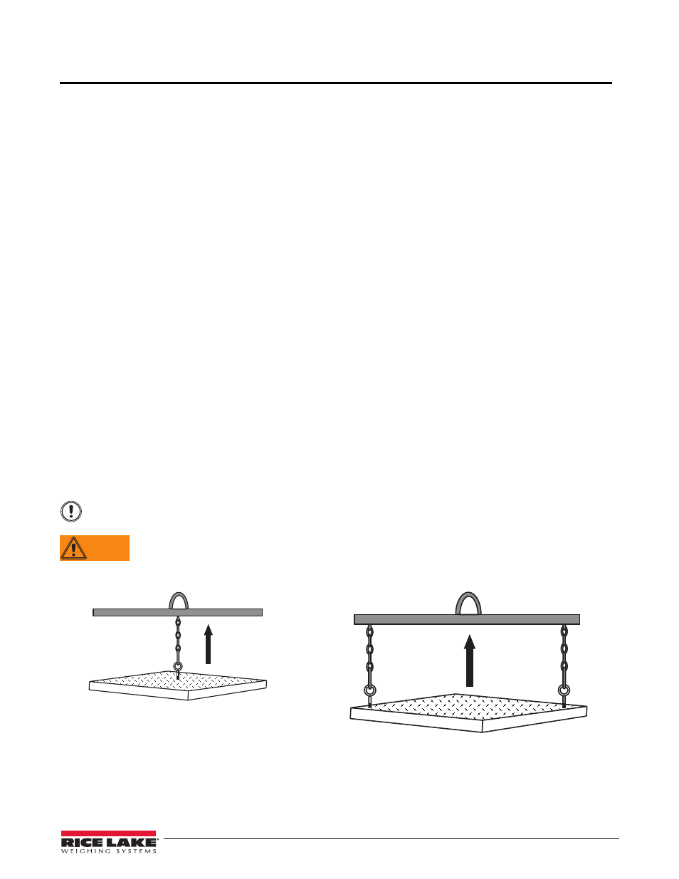
Remove all packing material and inspect scale for visible damage caused during shipment.
All
RoughDeck
models have threaded holes in the deck to allow installation of eye bolts with shoulders for use
when lifting the scale with chains or using a spreader bar.
Large Platform
(Larger then 5
’ x 5’, and /or more than 10,000lb capacity)
Use two 3/4
” eye bolts, insert into threaded holes in
opposite corners of top plate for lifting.
Small Platform
(5
’ x 5’ or smaller and/or 10,000lb or less capacity)
Use one 1/2
” eye bolt, insert into threaded hole in
center of top plate for lifting.
WARNING
Important
Lift the scale only with a properly designed spreader bar as shown in Figure 2-1.
Lifting force must be vertical to avoid bending the eye bolts.
Eye bolts must always be inserted into the top of the scale. Lifting should always occur with
the top plate facing up and the eye bolts securely attached through the nuts welded to the
bottom side of the top plate. Lifting from the bottom of the plate could cause nuts to break
loose and the scale to fall.
Figure 2-1. Proper Lifting Technique