4 assembly, 1 installing and adjusting feet, 5 junction box connections – Rice Lake RoughDeck AX User Manual
Page 8: Installing and adjusting feet, Inch of level, The roughdeck ax uses the tuffseal, Figure 2-2. expansion port wiring location, 30 roughdeck he autolift
30
RoughDeck HE AutoLift
2.4
Assembly
The following paragraph presents instructions for installing and adjusting the scale feet.
2.4.1
Installing and Adjusting Feet
For load cell protection during shipping, the scale feet are shipped detached from the load cells. The feet are
secured to the bottom of the shipping pallet along with the load cell cable, strain relief fitting and product literature.
Remove all parts from the envelope.
Screw one foot into each load cell and turn all the way in until the foot touches either the load cell or the underside
of the deck. Then unscrew each foot three complete turns.
Place a spirit level on the deck. Adjust any “high” corners not in contact with the floor by further unscrewing the
feet on those corners until they just contact the floor surface. When all feet are in contact with the floor, check the
deck with the spirit level to be sure the scale is within
1
/
4
inch of level.
2.5
Junction Box Connections
The RoughDeck AX uses the TuffSeal
®
4-channel signal trim junction box. It comes in a stainless steel enclosure.
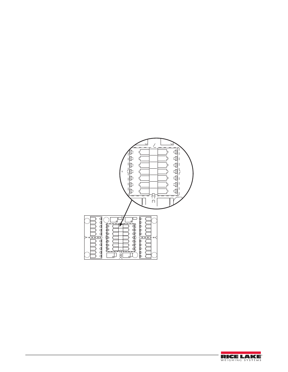
The TuffSeal junction box has been designed to connect and trim up to four load cells per board. However, it is
possible to use this box with other combinations. Use the expansion port on the main board (shown below), to
connect multiple junction boxes in series to accommodate applications that have more than four load cells
+1
15
15
+1
+1
15
&91
15
+1
$&--
$&--
$&--
$&--
*/%
&9
4*
4)%
4*
&9
.
4*
4$
4*
&9
&9
4*
4)%
4*
&9
&9
4*
4)%
4*
&9
4*
4*
&9
4)%
&9
4)%
&9
4&
4&
&91
*/%
4*
4*
&9
4)%
&9
4&
4&
.
Figure 2-2. Expansion Port Wiring Location
After determining the wiring pattern, route the load cell cables through the cord grip assemblies and leave the grips
loose until final closure. Before connecting load cell wires to the terminals, strip the wire insulation back 1/4” to
expose the wire. The spring-loaded terminals will accommodate 12-28 gauge wire. To connect the load cell wires
to the appropriate connectors, push in the quick-connect lever with a small screwdriver. While holding the lever,
insert the appropriate wire into the exposed wire opening. Release the screwdriver to allow the spring-loaded gate
to close and lock the wire in place.
The indicator terminal strip is used to connect the main cable to the indicator. Determine the indicator’s load cell
input connections from the indicator operating manual. Run a cable from your indicator terminal into the junction
box through the larger cord grip and make the connection.