Figure 6-1 – Rice Lake Farm Bars - KLU Series Universal Weighbars User Manual
Page 15
Troubleshooting
11
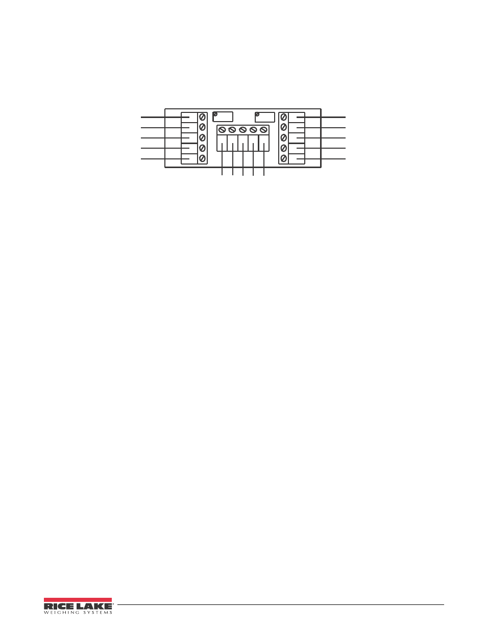
To check a load bar separately, it must be completely disconnected from the scale's electrical circuit. This is
accomplished by disconnecting the load bar at the scale's junction box, Figure 6-1. However if the junction box
contains a Weights & Measures seal, consult your scale dealer before proceeding. To disconnect a load bar, loosen
the screws on the circuit board for the load bar in question, and remove the wires. Resistance measurements can
now be taken as shown in Table 6-1, and should correspond with the values in the "One Load Bar" column in the
same way as described above. If not, consult your scale dealer. The dealer may ask you to check the individual load
cells.
Wire from
Load Bar 1
Black (-EX)
Green (+SIG)
Red (+EX)
White (-SIG)
Shield
Black (-EX)
Green (+SIG)
Red (+EX)
White (-SIG)
Shield
Wire from
Load Bar 2
Black (-EX)
Gr
een (+SIG)
Red (+EX)
White (-SIG)
Shield
Wire to Instrument
Figure 6-1. Junction Box Wire
When checking an individual load cell, it must be completely disconnected from the scale's electrical circuit. To
accomplish this, the wires will need to be taken apart at the load bar cable splice. See Figure 6-2 for the wiring of a
load bar system. The circuit diagram for the Load Cells of a single load bar is shown in Figure 6-4. Remember that
each load cell contains five wires, but each load bar has only four wires running to the junction box. All five wires
must be disconnected to separate that load cell from the circuit.