0 troubleshooting, 1 general, 2 drifting – Rice Lake Farm Bars - KLU Series Universal Weighbars User Manual
Page 14: 3 abnormally large reading, Troubleshooting
10
KLU Series Universal Weighbars Operator’s Manual
6.0
Troubleshooting
6.1
General
If you are having trouble with your load bars, a few simple procedures should help you determine where the
problem lies. First, inspect the scale for any physical damage. Take special note of the cable and connectors.
Wiggle the cables and connectors while watching the indicator display. If the readout jumps while moving a cable
or connector, there is likely a short or loose connection. Repair or replace the cable or connector as appropriate.
6.2
Drifting
If the scale readout is drifting, moisture may be present somewhere in the scale's electrical circuit. Check for
moisture in any of the connectors, junction boxes, or load bars. Dry any location where you suspect moisture is
present. If you find a location where moisture is collecting on a regular basis, seal the location with a waterproof
sealant.
6.3
Abnormally Large Reading
If the indicator shows a very large number and the readout cannot be changed using the indicators zero adjustment,
there may be a problem in the circuit. To locate this type of problem, a series of electrical resistance measurements
must be made. To perform these checks, you will need an accurate ohmmeter and a soldering iron.
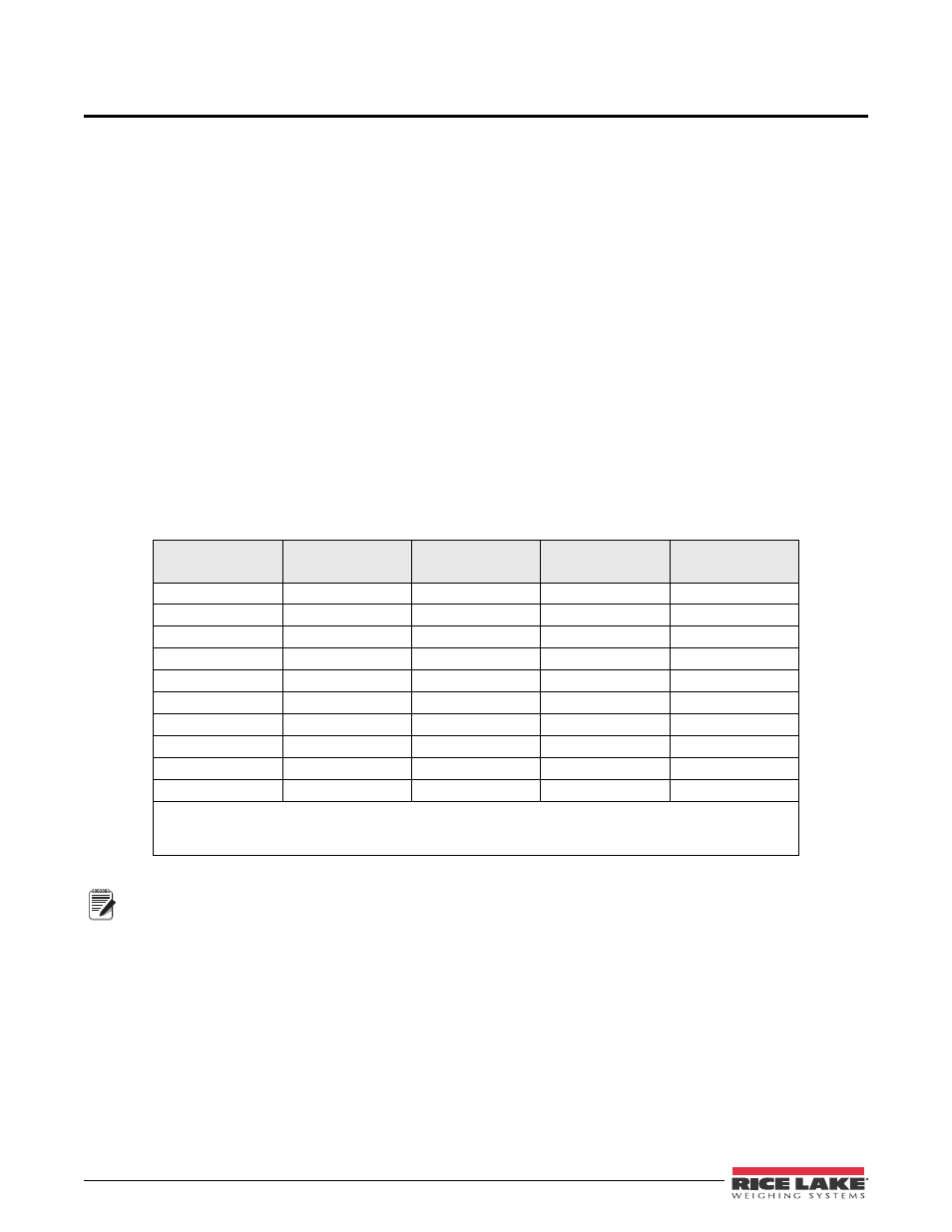
To locate a faulty component with the ohmmeter, start by taking readings in the connector that plugs into the
indicator cable (this is the cable the runs into your scale). The connector has four pins labelled A, B, C and D, the
following chart lists the appropriate resistance readings. Remember, when making this type of measurement the
power must be OFF. Further, be careful that your fingers are not making contact with the probes on the ohmmeter
– if they are, the reading you take may be incorrect.
Table 6-1. Ohmmeter Readings
*Wire Color
Connector Pin
2-Load Bar
System
**One Load Bar
***Single Load
Cell
White – Red
D – C
145
Ω
290
Ω
395
Ω
White-Green
D – B
175
Ω
350
Ω
350
Ω
White-Black
D – A
145
Ω
290
Ω
395
Ω
Black-Green
A – B
145
Ω
290
Ω
45
Ω
Black-Red
A – C
197.5
Ω
395
Ω
790
Ω
Green-Red
B – C
145
Ω
290
Ω
745
Ω
White-Brown
350
Ω
Brown-Red
45
Ω
Black-GND
>10M
Ω
>10M
Ω
>10M
Ω
GND-Frame
0
0
0
*See Figure 6-1
**Valid only if Loadbar is disconnected from rest of circuit.
***Valid only if Load Cell is disconnected from rest of circuit.
Note
This chart is only valid at a temperature of 22°C. Resistance will vary slightly with temperature.
The readings in Table 6-1 should be within 5 ohms of the value shown. The readings are slightly temperature
dependent and as a result will not match Table 6-1 exactly. However, all the readings you take should differ from
the table by the same percentage. For example, if the resistance across pins D & C reads 142Ω ±1Ω, resistance
across pins D & A should also read 142Ω ±1Ω. In other words the values equal in Table 6-1 should also be equal
when you take your measurements. If the readings correspond to the values in the table an electrical problem in the
scale is not likely. If any readings across pins of the connector differ from the chart, each load cell must be checked
individually.