3 leveling, 3 enclosure disassembly, 4 cable assembly instructions – Rice Lake Counterpart Configurable Counting Indicator - User Manual Rev. D - Version 2.4 User Manual
Page 15: Leveling
Installation
9
2.2.3
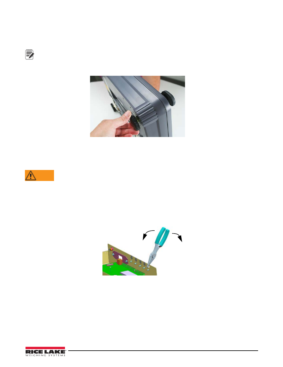
Leveling
Select a location for the Counterpart that is reasonably level and free of vibrations and air currents. Adjust the four
corner feet on the scale base and refer to the bubble level on the inside frame. The base should not rock and the feet
should have solid contact with the surface.
Note
Ensure the nut on each foot’s bolt is secured flush against the scale base.
To ensure greater scale stability, turn in all four adjustable legs before leveling. Turn out adjustable legs to level as
needed.
Figure 2-3. Adjust the Scale Base Feet
2.3
Enclosure Disassembly
The Counterpart indicator enclosure must be opened to connect cables for load cells, communications, and digital
inputs/outputs.
WARNING
Before opening the unit, ensure the unit is turned off and the power cord is disconnected from the power
outlet. The power outlet must be located near the indicator to allow the operator to easily disconnect
power to the unit.
Ensure power to the indicator is disconnected, then place the indicator on an anti static mat. Remove the four
screws holding the top plate to the enclosure body and set them aside. Gently lift the top plate away from the
enclosure and disconnect any cables and set it aside.
2.4
Cable Assembly Instructions
The indicator comes with five removable openings for running cabling through. The user can open as many as
needed and can easily remove them by using needle-nose pliers as shown in Figure 2-4.
Choose which
openings to use.
Figure 2-4. Removable Openings
Use the following steps to open and install cable assemblies.
1. Open the cover assembly by removing the four screws (only one shown in Figure 2-5).
2. Run the appropriate cable(s) through the desired opening(s).
3. Thread the plastic split bushing (found in the parts kits contents) onto the cable with the smallest diameter
facing towards the enclosure and the split opening facing downwards.
4. Replace the cover assembly and tighten using the four screws.