8 fldbus menu, Fldbus menu, S e c t i o n 3 . 2 . 8 o n p a g e 4 9 – Rice Lake 920i Installation Manual V3.08 User Manual
Page 55
Configuration
49
3.2.8
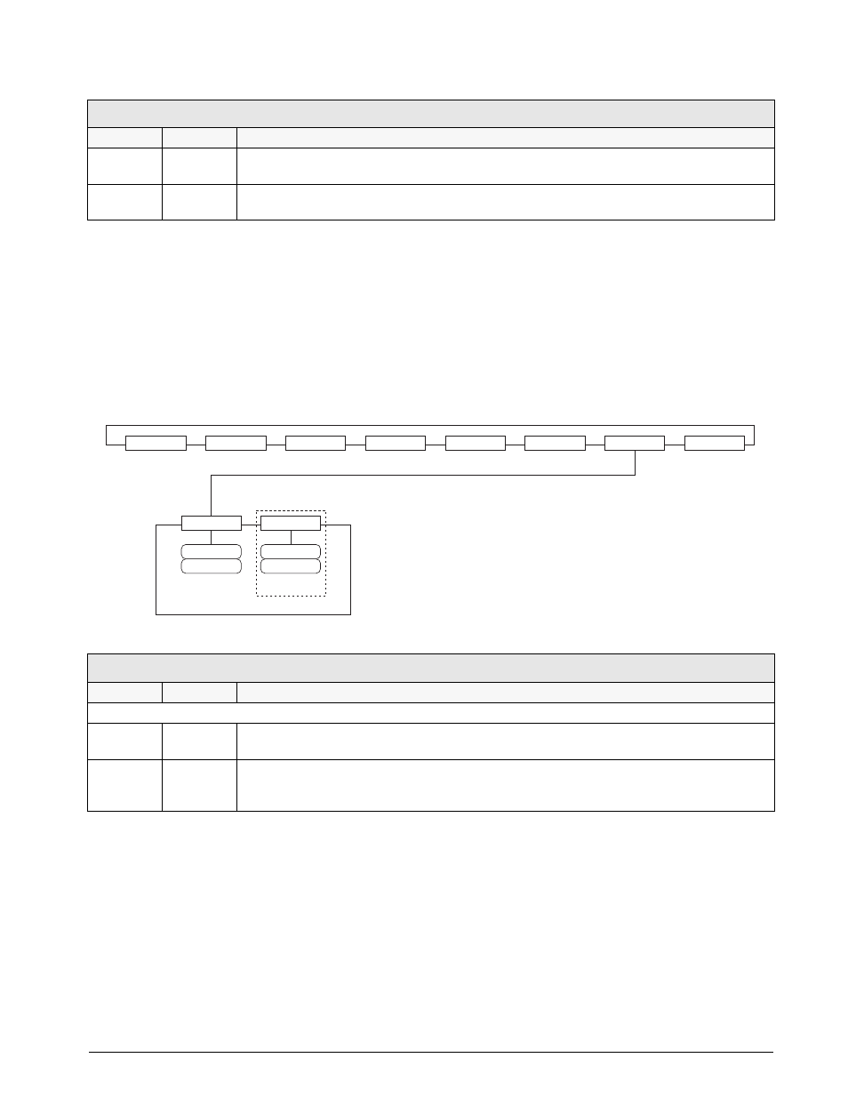
FLDBUS Menu
The FLDBUS menu is shown only if a DeviceNet, Profibus, EtherNet/IP, or ControlNet option card is installed.
The SWAP parameter on the FLDBUS menu enables byte swapping by the
iRite
BusCommand handler rather
than requiring a SWP (SWAPBYTE) instruction in the PLC. Byte swapping is enabled by default for DeviceNet
cards; for all other fieldbus cards, byte swapping is disabled by default.
The DATASIZE parameter sets the size of the BusCommand handler data transfers. The default value (8 bytes, or
4 words) matches the default data size specified in the EDS and GSD files, and used by the standard discrete
transfer commands. DATASIZE can be set to any value from 2–128 bytes (1–64 words), but the value specified
must match the data size set for the PLC Scanner I/O data size.
Figure 3-18. FLDBUS Menu
TWZERO
40
0–65535
Tweak zero. Enter tweak value to adjust the analog output zero calibration. Use a multimeter to
monitor the analog output value.
TWSPAN
59650
0-65535
Tweak span. Enter tweak value to adjust the analog output span calibration. Use a multimeter to
monitor the analog output value.
FLDBUS Menu
Parameter
Choices
Description
Level 2 submenus
SWAP
YES
NO
Specifies whether byte-swapping is enabled. For DeviceNet cards, this parameter defaults to YES;
for all other cards the default value is NO.
DATASIZE
8
2-128
Specifies the data size, in bytes, that the BusCommand handler transfers. If this parameter is set to
a value other than the default (8 bytes), ensure that it matches the Scanner I/O data size specified
for the PLC.
ALGOUT Menu
Parameter
Choices
Description
Table 3-11. Analog Output Menu Parameters
SCALES
SERIAL
FEATURE
PFORMT
SETPTS
DIG I/O
FLDBUS
VERS
SWAP
YES
NO
DATASIZE
8
data_size
If SWAP = YES