8 fuse replacement, 9 battery replacement, 10 parts kit contents – Rice Lake 920i Installation Manual V3.05 User Manual
Page 20
14
920i
Installation Manual
2.8
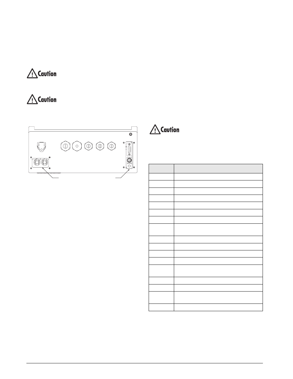
Fuse Replacement
Fuses for the universal and deep enclosure models of
the
920i
are located under a cover plate on the outside
of the enclosure. Remove the cover plate, replace the
fuses, and reinstall the cover plate (see Figure 2-13).
To protect against the risk of fire, replace
fuses only with same type and rating fuse.
See Section 10.14 on page 122 for
complete fuse specifications.
Interface board and fuse access cover
plates must be in place for use in NEMA
4X/IP66 applications.
l
Figure 2-13. Interface Board and Fuse Locations,
Universal Model
2.9
Battery Replacement
The lithium battery on the CPU board maintains the
real-time clock and protects data stored in the system
RAM when the indicator is not connected to AC
power.
Data protected by the CPU board battery includes
time and date, truck and tare memory, onboard
database information, and setpoint configuration.
Use
iRev
to store a copy of the indicator configuration
on a PC before attempting battery replacement. If any
data is lost, the indicator configuration can be restored
from the PC.
NOTE: Memory option card data is also protected by a
lithium battery. All database information stored on a memory
card is lost if the memory card battery fails.
Watch for the low battery warning on the LCD display
and periodically check the battery voltage on both the
CPU board and on any installed memory option cards.
Batteries should be replaced when the indicator low
battery warning comes on, or when battery voltage
falls to 2.2 VDC. Life expectancy of the battery is ten
years.
Replacement Procedure
For best results, replace the battery while in weigh
mode and with AC power applied. Use care not to
bend the battery retaining spring.
If the battery must be replaced with power removed,
do the following immediately after restoring power:
1. Place indicator in setup mode.
2. Go to the Version Menu and press the
Reset
C o n f i g
softkey. If connected using
i Re v
,
configuration can be reset by using monitor
mode to enter the RESETCONFIGURATION
command followed by the RS command.
See Figure 2-5 on page 10 for CPU board battery
location and orientation (positive side up).
Risk of explosion if battery is replaced
with incorrect type. Dispose of batteries
per manufacturer instruction.
2.10 Parts Kit Contents
Table 2-6 lists the parts kit contents for the universal
model of the
920i
.
Torque fuse and interface board access covers to
8 in-lb (0.90 N-m)
Fuses
F1 & F2
Interface Board
PN
Description
14626
Kep nuts, 8-32NC (4)
14862
Machine screws, 8-32NC x 3/8 (12)
75068
Sealing washers (14)
15133
Lock washers, No. 8, Type A (4)
30623
Machine screws, 8-32NC x 7/16 (2)
15631
Cable ties (4–single A/D, 6–dual A/D)
15665
Reducing glands for 1/2 NPT cord grips (2)
15887
6-position screw terminal for load cell
connection (1–single A/D, 2–dual A/D)
19538
Cord grip plugs (4–single A/D, 3–dual A/D)
42350
Capacity label (1–single A/D, 2–dual A/D)
53075
Cable shield ground clamps (4)
70599
6-position screw terminals for J2 and J10 (2)
71126
4-position screw terminal for J9 and optional
keyboard connection (2)
71125
3-position screw terminal for J11 (1)
42149
Rubber feet for tilt stand (4)
15144
Nylon washers for tilt stand, 1/4 x 1 x 1/16 (2,
universal model only)
68403
Wing knobs for tilt stand (2)
Table 2-6. Parts Kit Contents