4 led status indicators – Rice Lake 920i Programmable HMI Indicator/Controller - ControlNet Interface User Manual
Page 8
4
ControlNet Installation and Programming Manual
2.4
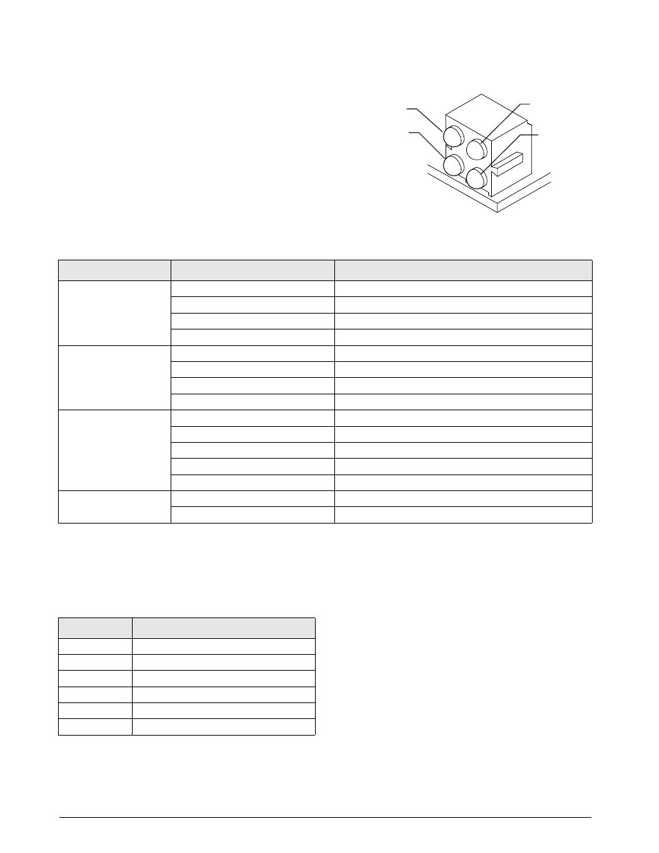
LED Status Indicators
An LED array on the ControlNet module provides
status information for troubleshooting. LED 1
provides module status; LED 2 provides status
information for both Channel A and B; LED 3
provides status information that can apply to either
channel; LED 4 indicates the presence of a network
connection to the module.
Table 2-1 on page 4 summarizes the function of the
module and network status LEDs.
Figure 2-5. ControlNet Status LED Module
A single bi-color watchdog LED on the surface of the
ControlNet module provides diagnostic information
for debugging the module itself. Table 2-2 lists the
indications provided by the debugging LED.
1
2
3
4
Module Owned
Channel A
Channel B
Module Status
LED
Status
Description
LED 1
Module Status
Steady Green
Connection in run state
Flashing Green
Connecting, connection idle
Steady Red
Major fault
Flashing Red
Minor fault
LED 2
Channel A and B
Off
Module not initialized
Steady Red
Major fault
Flashing Red
Node configuration error
Alternating Red/Green
Self-test
LED 3
Channel A or B
Off
Channel disabled
Steady Green
Normal channel operation
Flashing Green
Temporary error (node will self-correct) or not configured
Flashing Red
No other nodes, or media fault
Alternating Red/Green
Network configuration error
LED 4
Module Owned
Off
No connection opened
Steady Green
Connection opened
Table 2-1. Module and Network Status LED Indications
Status
Description
Off
No power
Red, 4Hz
DPRAM check fault
Red, 2Hz
ASIC and FLASH ROM check fault
Red, 1Hz
RAM check fault
Green, 2Hz
Module not initialized
Green, 1Hz
Module initialized and running
Table 2-2. Debugging LED Indications