2 installing controlnet option in the 520, 2 controlnet network connections, 3 address and termination switches – Rice Lake 920i Programmable HMI Indicator/Controller - ControlNet Interface User Manual
Page 7: Installing controlnet option in the 520, Section 2.3 on, X1 x10, Address switches, J2 controlnet module, W arning
Installation
3
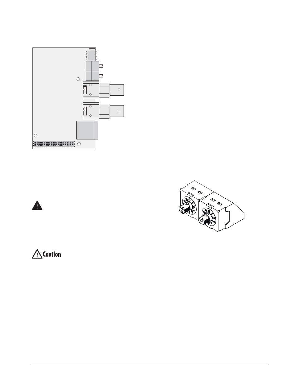
Figure 2-3. ControlNet Module
2.1.2
Installing ControlNet Option in the 520
Use the following procedure to install the ControlNet
Interface in the
520
indicator:
1. Disconnect indicator from power source.
Disconnect power before removing
indicator enclosure cover.
The
520
has no on/off switch. Before
opening the unit, ensure the power cord is
disconnected from the power outlet.
2. Place indicator on an antistatic work mat.
Remove screws that hold the enclosure cover
to the enclosure body.
Use a wrist strap to ground yourself and
protect components from electrostatic
discharge (ESD) when working inside the
indicator enclosure.
3. Carefully align the large option card
connector with connector J2 on the CPU
board. Press
down
to seat the option card in
the CPU board connector.
4. Use screws provided in the option kit to
secure the other end of the option card to the
threaded standoffs on the CPU board.
5. Route cables through cover supplied with the
option kit.
6. Reconnect power to the indicator.
7. The indicator automatically recognizes all
installed option cards when the unit is
p o w e r e d o n . N o h a r d w a r e - s p e c i f i c
configuration is required to identify the
newly-installed ControlNet interface to the
system.
2.2
ControlNet Network Connections
The ControlNet module includes the following
connectors:
•
Network Access Port (NAP), for temporary
diagnostic or configuration access
•
Two BNC connectors for ControlNet
Channels A and B
Feed ControlNet network cables through cord grip
(
720i
,
820i
and
920i
) or through the special cover
supplied for the
520
. Allow enough cable for routing
along inside of enclosure to connector on the
ControlNet module. Connect network cables to
connector on the ControlNet module (see Figure 2-3),
then use cable ties to secure network cables to the
cable tie mounts.
2.3
Address and Termination Switches
The ControlNet Interface address is set using switches
on the Profibus module. Figure 2-4 shows the address
and termination switches.
Figure 2-4. ControlNet Module Address Switches
Address Switches
Two rotary switches are used to set the decimal node
address, 1–99, of the ControlNet Interface (use
Address 0 if configuring the address in software.)
Note that the node address cannot be changed during
operation.
The left switch shown in Figure 2-4, marked
x10
, sets
the tens digit; the right switch,
x1
, sets the units digit.
(For example, to set a decimal address of 14, set
x10 =
1,
and
x1 = 4
.)
J2
ControlNet
Module
Network Access Port
(NAP)
ControlNet
Channel A
ControlNet
Channel B
MacID
Switches
x1
x10
LED Status Indicators
W arning
x1
x10
Address
switches