Optional interfaces on the front side – Kontron KBox A-101 Users Guide User Manual
Page 16
7. Product Description
KBox A-101 – User’s Guide (preliminary Version 1.00)
7.1.4.
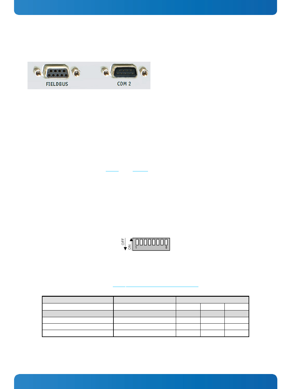
Optional Interfaces on the Front Side
Fig. 12:Optional external interfaces routed from the onboard ports (on the front side)
The optional interfaces (Fieldbus and COM 2) on the front side of the KBox A-101 must be ordered separately. The following
interfaces are available:
•
Fieldbus interface: LPCtoCAN or PROFIBUS (Please note: With PROFIBUS, optional WLAN is not available!)
•
COM 2-interface: RS232 or RS422/485 (non-isolated)
7.1.4.1.
RS422/RS485 Serial Interface
The optional serial RS422/485 interface (Fig. 9, pos. 6; Fig. 12) consists of a 9-pin D-SUB connector. The interface can be
configured via an on-board DIP switch (SW1) for RS422 or RS485 serial communication.
The optional settings (SW1) for RS485 mode communication allow the system’s operation either in full duplex mode or in
half duplex mode (see tables on the next page). While running in RS485 half duplex mode the system stays permanently in
a receiver mode. The switch to transmission mode will be done automatically. The user can determine if the automatic
mode switch to transmission mode should be triggered by the RTS-line or should be triggered by the last sent message
using the TxD line.
If triggered by RTS has been selected, then the RTS-signal must be activated by the application software before
transmission of the data packets starts; and RTS signal has to be disabled again after termination of data transmission.
If TxD line will be used for the mode transceiver switch process, the receiver device has to follow a timeout before starting
to send any data.
Fig. 13: Onboard DIP switch (SW1) with DP1 up to DP8 for RS422/RS485serial communication settings
In order to configure this interface for serial communication (as RS422 or RS485) corresponding to your requirements, set
the switches of the DIP switch (SW1) to “ON” or “OFF” (factory settings are marked grey). For accessing the DIP switch refer
to the procedure described in the subsection 9.3.1 “Opening and Closing the KBox A-101”.
Serial Communication Type
Transmitting<->receiving
SW1 Settings
DIP1
DIP2
DIP3
RS422 4-Channel Mode
-
OFF
OFF
OFF
RS485 4-Wire Mode (Bus-Master)
-
ON
OFF
ON
RS485 2-Wire Mode
RTS
ON
ON
ON
RS485 2-Wire Mode
Timeout
ON
ON
OFF
14
www.kontron.com