Front side, Dc in – direct current connector, Controls and indicators – Kontron KBox A-101 Users Guide User Manual
Page 13: Fig. 9: kbox a-101 - front view, Fig. 10: kbox a-101 - controls and indicators
7. Product Description
KBox A-101 – User’s Guide (Version 1.00)
7.1.
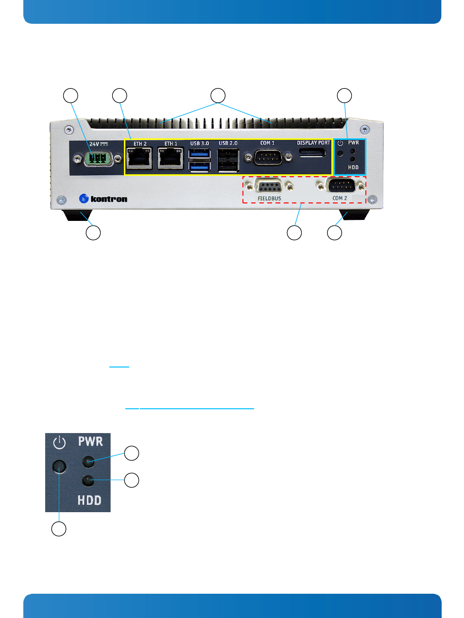
Front Side
Fig. 9: KBox A-101 - front view
1
DC IN power connector
2
External connectors of the installed SBC
3
Cooling fins
4
Controls and indicators
5
Rubber feet
6
External interface connectors (optionally routed from the
on board interfaces)
7.1.1.
DC IN – Direct Current Connector
The 3-pin connector (Fig. 9, pos. 1) provides the power connection of the KBox A-101 to the appropriate main power
supply:
DC power supply: using a corresponding power cord (only the Phoenix connector is included).
Please observe the section 8.1 “Connecting to DC Main Power Supply”.
7.1.2.
Controls and Indicators
Fig. 10: KBox A-101 - Controls and indicators
1
Power button
2
Power LED
3
HDD LED
1
2
3
6
5
5
3
4
1
2
+
N.C.
-
www.kontron.com
11