Connector descriptions – bottom, Lpc/pod interface – x34, Backlight connector – x12 – Kontron MSM-LP Manual User Guide V106 User Manual
Page 24: 4 connector descriptions – bottom, 1 lpc/pod interface – x34, 2 backlight connector – x12
MSM-LP / MSM-LP Connectors & Jumpers
www.kontron.com
20
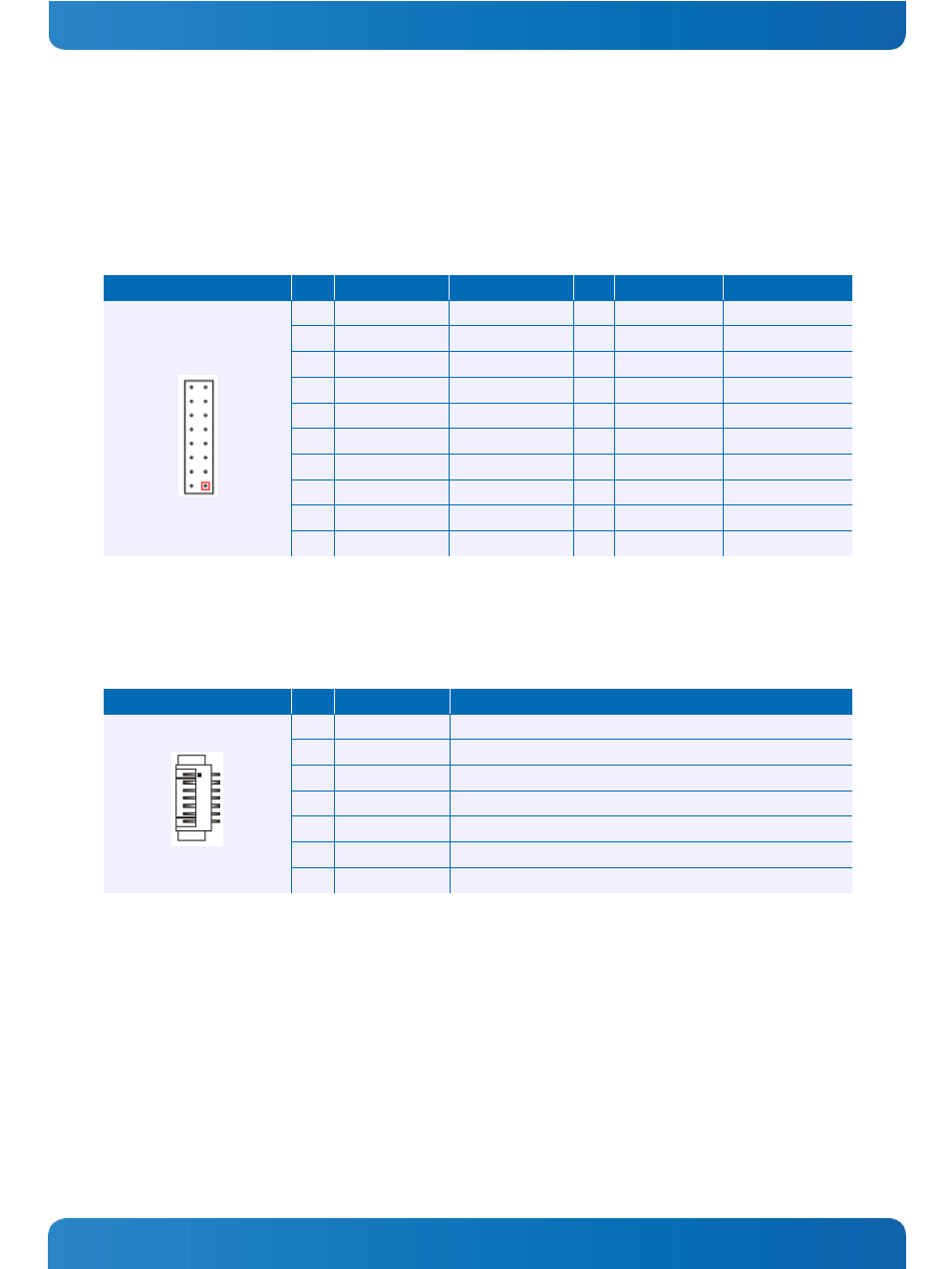
3.4 Connector Descriptions – Bottom
3.4.1 LPC/POD Interface – X34
This is a connector for additional LPC devices such as POD, SuperIO or TPM. It can also be used for a second BIOS flash
interface (SPI or LPC)
Header
Pin
Signal Name
Function
Pin
Signal Name
Function
2.00mm grid
1
V3.3_S0
Power
2
LPC_LDA0
Data
3
LFRAME#
LPC frame
4
LPC_LDA1
Data
5
PLT_RST#
Reset OUT
6
LPC_LDA2
Data
7
V3.3_S0
Power
8
LPC_LDA3
Data
9
V5.0_S0
Power
10
PLT_RST#
Reset OUT
11
CLK
Clock
12
BIOS_EN
BIOS selection
13
GND
Ground
14
RESET_IN#
Reset IN
15
V3.3_SPI_PROG
Power IN
16
SERIRQ
17
SPI_CS#
18
SPI_CLK
19
SPI_MISO
20
SPI_MOSI
3.4.2 Backlight Connector – X12
The backlight connector is always mounted on the bottom side, opposite of the LVDS
Header
Pin
Signal Name
Function
1
NC
Not connected
2
BKLTADJ
Brightness control (PWM 3.3 V)
3
GND
Ground
4
NC
Backlight power +5V *)
5
NC
Backlight power +5V *)
6
GND
Ground
7
BKLTON
Backlight on/off
*) Backlight power can be set to +12V by assembly option (needs +12V on pin 1 of supply connector X1).