Power supply – x1, Usb interfaces – x50/x51, 5 power supply – x1 – Kontron MSM-LP Manual User Guide V106 User Manual
Page 18
MSM-LP / MSM-LP Connectors & Jumpers
www.kontron.com
14
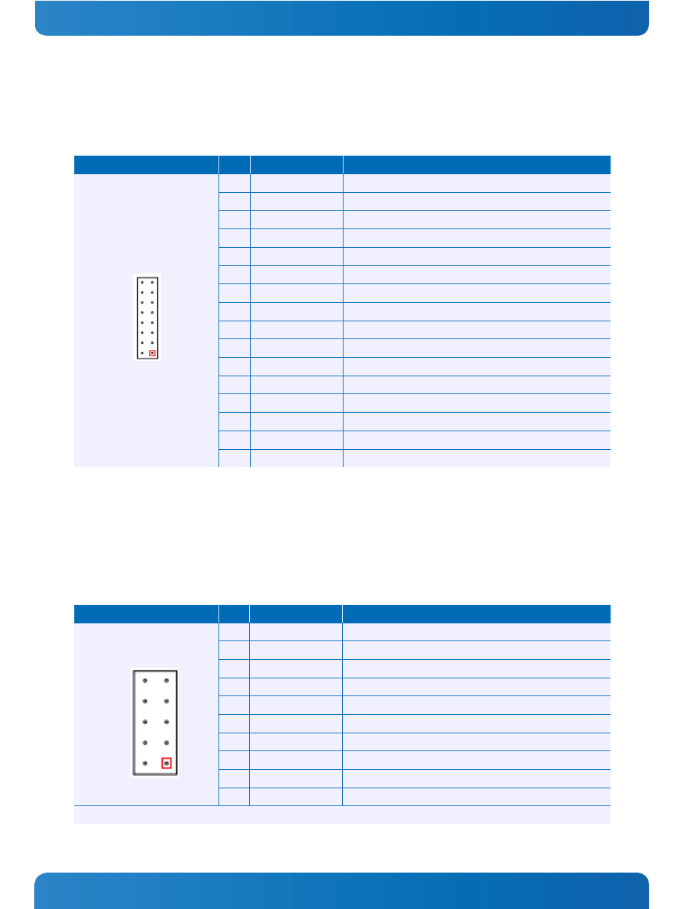
3.2.5 Power Supply – X1
A power connector for the main power supply is provided. The SBCs function with a single +5V power supply.
Additional voltages for PC/104 peripherals (+12V, -5V, -12V) must be generated externally.
Header
Pin
Signal Name
Function
2.00mm grid
1
+12V_IN
Power +12V
2
*)
PSON#
ATX power on (Power LED)
3
+5V_IN
Power +5V
4
+5V_IN
Power +5V
5
GND
Ground
6
GND
Ground
7
GND
Ground
8
GND
Ground
9
POWER_BTN#
External main button
10
RESET_BTN#
External reset button
11
*)
IGNITION#
Ignition input
12
HDD_ACT#
HDD activity LED
13
VBAT
RTC battery input
14
SMB_ALERT#
System management alert
15
SMB_DAT
System management bus data
16
SMB_CLK
System management bus clock
*) Warning: On system board the pin out changes!
Pin 2 PSON# is the SLP_S5# 3.3 Volt output and Pin 11 EC_IGNITION# is the SLP_S3# 3.3 Volt output.
3.2.6 USB Interfaces – X50/X51
The board is populated with four USB interfaces. Two connectors with 2 USB ports each are defined. Further USB ports
are accessible over the PCIe/104 extension connector.
Header
Pin
Signal Name
Function
2.54mm grid
1
USBxVCC
Power +5V
2
USByVCC
Power +5V
3
USBxN
USBx data negative
4
USByN
USBy data negative
5
USBxP
USBx data positive
6
USByP
USBy data positive
7
GND
Ground
8
GND
Ground
9
SHD
Shield
10
SHD
Shield
x (y) is the number of the USB port (USB1: x -> 1)