4 power front panel header, Ktt20/pitx user's guide, 1 power led – Kontron KTT20-pITX User Manual
Page 38
KTD-S0044-G
Page 34
Power Supply
KTT20/pITX User's Guide
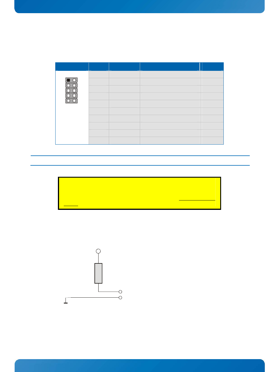
15.4 Power Front Panel Header
The power button and other power signals are available through the pin header J900 (10 pins).
Header
Pin
Signal
Description
Type
1
RST_BTN+
Reset button (positive)
I-18
2
PWR_BTN+
Power button (positive)
I-18
3
RST_BTN-
Reset button (negative) = GND
PWR
4
PWR_BTN-
Power button (negative) = GND
PWR
5
POWER_LED-
Power LED (negative) = GND
PWR
6
RSVD
Reserved
---
7
POWER_LED+
Power LED (positive)
O-33 / PWR
8
RSVD
Reserved
---
9
RSVD
Reserved
---
1
2
9
10
10
RSVD
Reserved
---
Note:
1)
The label PWR_BTN (power button) is identical with NVIDIAs
®
'ONKEY' button.
CAUTION!
If you apply a discrete logic circuit instead the standard buttons to control the
reset respectively power button inputs then you should use open drain outputs
without a pullup resistor.
15.4.1 Power
LED
The following picture illustrates the onboard wiring.
+3.3V
220R
C
o
nn
e
c
to
r
+
-
Power LED -
Power LED +