3 connector 1, Ktt20/pitx user's guide – Kontron KTT20-pITX User Manual
Page 33
KTD-S0044-G
Page 29
Digital I/O Interface
KTT20/pITX User's Guide
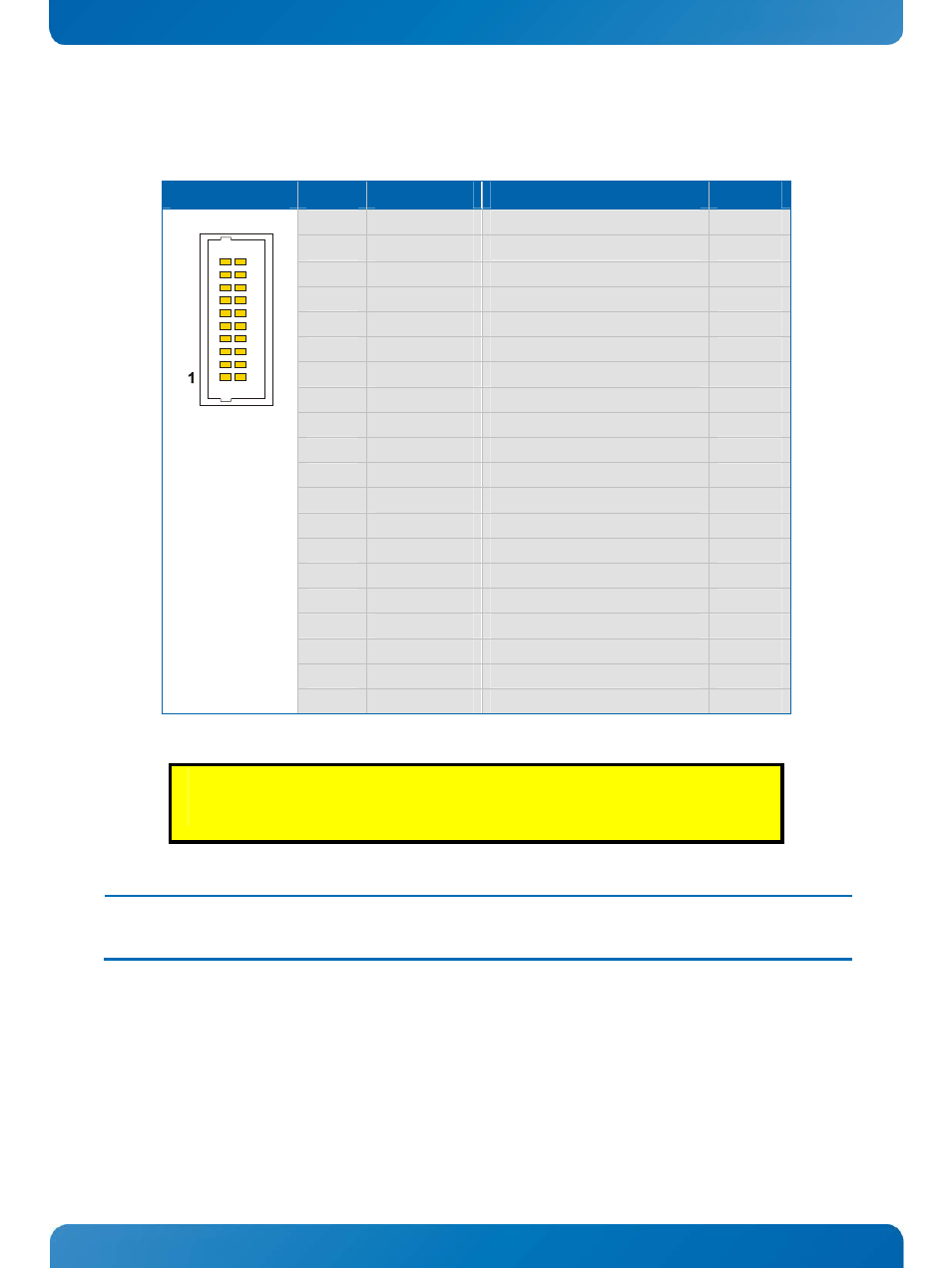
14.3 Connector 1
The digital I/O interface with I/O voltage 1.8V is available through the connector J1300 (20 pins).
Header
Pin
Signal
Description
Type
1
VCC1
1)
Power +1.8V
PWR
2
VCC1
1)
Power +1.8V
PWR
3
GPIO0
I/O
R.05 or keyboard row 5
IO-18
4
GPIO1
I/O
R.06 or keyboard row 6
IO-18
5
GPIO2
I/O
R.07 or keyboard row 7
IO-18
6
GPIO3
I/O
S.00 or keyboard row 8
IO-18
7
GPIO4
I/O
S.01 or keyboard row 9
IO-18
8
GPIO5
I/O
S.02 or keyboard row 10
IO-18
9
GPIO6
I/O
S.04 or keyboard row 12
IO-18
10
GPIO7
I/O
S.05 or keyboard row 13
IO-18
11
GPIO8
I/O
Q.00 or keyboard column 0
IO-18
12
GPIO9
I/O
Q.01 or keyboard column 1
IO-18
13
GPIO10
I/O
Q.02 or keyboard column 2
IO-18
14
GPIO11
I/O
Q.03 or keyboard column 3
IO-18
15
GPIO12
I/O
Q.04 or keyboard column 4
IO-18
16
GPIO13
I/O
Q.05 or keyboard column 5
IO-18
17
GPIO14
I/O
Q.06 or keyboard column 6
IO-18
18
GPIO15
I/O
Q.07 or keyboard column 7
IO-18
19
GND
Ground
PWR
20
GND
Ground
PWR
CAUTION!
Do not use signal voltages above 1.8V. All I/O signals are unprotected against overvoltage.
Note:
1)
To protect the external power lines of peripheral devices make sure that
- the wires have the right diameter to withstand the maximum available current.
- to enclosure of the peripheral device fulfills the fire-protecting conditions of IEC/EN 60950.