5 analog ground usage, Analog ground usage - 5, Analog grounding - 5 – Kontron CP371 User Manual
Page 49: Cp371, Cp371 configuration
CP371
Configuration
ID 23762, Rev. 02
© 2002 PEP Modular Computers GmbH
Page 4 - 5
4.2.5
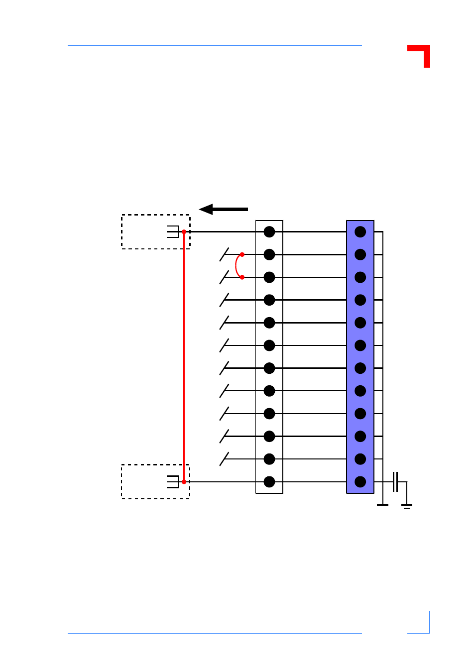
Analog Ground Usage
Analog ground usage must be carefully considered in order to avoid ground loops or floating
signals which can ultimately lead to the degradation of the system performance. The figure be-
low indicates the nominal analog grounding situation, but is, of course, very much subject to
the requirements of the application as a whole. What is important, however, is to ensure that
ground loops do not get created in the course of the wiring up of the various system compo-
nents. Additionally, it may be necessary to use heavier gauge wiring to avoid excessive loading
of single wires.
Figure 4-4: Analog Grounding
CON 2
CP371
PROCESS SIDE
Lines with X’s
indicate the type
of analog ground
connections
which should
not be made.
6
11
16
21
27
32
37
42
43
48
53
58
X
X
central
analog
grounding
point 1
central
analog
grounding
point n