3 system interfaces, 1 analog input interface, System interfaces - 6 – Kontron CP371 User Manual
Page 34: Analog input interface - 6, Functional description cp371, Channels
Functional Description
CP371
Page 2 - 6
© 2002 PEP Modular Computers GmbH
ID 23762, Rev. 02
2.3
System Interfaces
2.3.1
Analog Input Interface
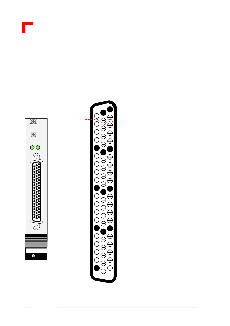
The analog input interface is accomplished through the CON2 connector. The following figure
and table indicate the pin layout and pinout of this connector.
Figure 2-2: Pin Layout of the Analog Input Interface Connector CON2
CP 371
0-7 8-15
I
I
I
I
I
I
I
I
I
I
I
I
I
I
I
I
1
22
43
CHANNELS
0
1
2
3
4
5
6
7
10
8
9
11
14
15
12
13
Pin Naming Convention:
●
Ground (analog)
+
Plus
-
Minus
I
I (current)
O
Pin not connected
Plus, minus, and I are names for
these pins and do not indicate
the polarity of the signal to be pre-
sented to the CP371.
LED’s
0-7
Cluster A activated
(Channels 0 to 7)
8-15 Cluster B activated
(Channels 8 to 15)
See also other documents in the category Kontron Hardware:
- CP3003-SA uEFI BIOS (72 pages)
- CP3003-SA (36 pages)
- CP3002 (38 pages)
- CP3002-RC uEFI (64 pages)
- CP-RIO3-05 (42 pages)
- CP3002-RC (30 pages)
- CP342 (52 pages)
- CP930 (46 pages)
- CP932 (52 pages)
- CP346 (72 pages)
- CP384 (66 pages)
- CP383 (74 pages)
- CP382 (58 pages)
- CP381 (60 pages)
- CP372 (64 pages)
- CP-RIO3-04S (38 pages)
- CP390 (36 pages)
- CPS3410 (9 pages)
- CPS3402 (9 pages)
- CPS3105 (9 pages)
- CPS3101 (9 pages)
- CPS3003-SA (19 pages)
- PB-SIO4 (34 pages)
- PB-SIO4A (34 pages)
- PB-DOUT8 (34 pages)
- VMOD-2 (82 pages)
- VSBC-32 (110 pages)
- VM42 (62 pages)
- Bootstrap Loader (24 pages)
- VMP1 with Netbootloader (120 pages)
- VMP1 (106 pages)
- NetBootLoader (86 pages)
- VMP2 (142 pages)
- VMP3 (154 pages)
- CP-RIO6-923 (32 pages)
- CP-RIO6-923-F (32 pages)
- CP-RIO6-001 (28 pages)
- CP-RIO6-001-HD-VGA (46 pages)
- CP-RIO6-M (20 pages)
- CP-RIO6-B (28 pages)
- CP6925 (42 pages)
- CP6002 uEFI BIOS (76 pages)
- CP6002 IPMI (40 pages)
- CP6002 (42 pages)