4 system relevant information, 1 system configuration, 2 driver software – Kontron CP371 User Manual
Page 22: 5 board diagrams, System relevant information - 6, System configuration - 6, Driver software - 6, Board diagrams - 6, Introduction cp371
Introduction
CP371
Page 1 - 6
© 2002 PEP Modular Computers GmbH
ID 23762, Rev. 02
1.4
System Relevant Information
The following system relevant information is general in nature but should still be considered
when developing applications using the CP371.
1.4.1
System Configuration
When implementing applications, precautions must be taken to ensure that the input signals
presented to the CP371 comply with the specifications set forth in this manual. For this reason
it will be necessary for most applications to provide signal conditioning prior to presenting the
analog input to the CP371. In addition, it is imperative that signal interference be kept to a min-
imum. Refer to chapters 4 and 5 for further information.
1.4.2
Driver Software
The CP371 is supplied with appropriate driver software which provides software interfacing to
the system master.
1.5
Board Diagrams
The following diagrams provide additional information concerning board functionality and com-
ponent layout.
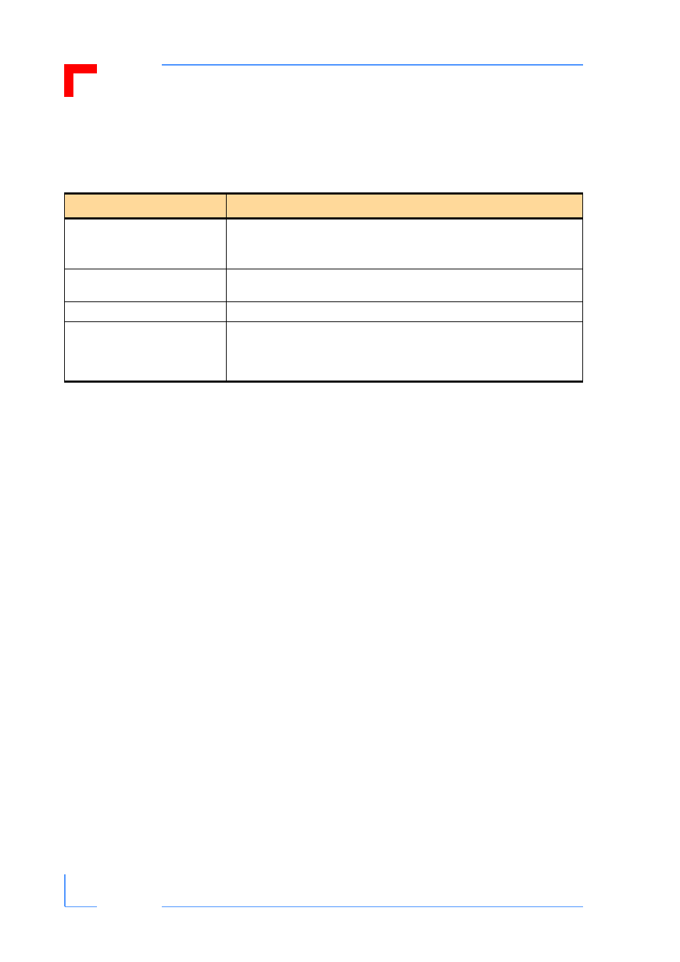
Table 1-2: System Relevant Information
SUBJECT
INFORMATION
System Configuration
The CP371 operates with a system clock frequency of 33 MHz.
The number of CP371’s which can be installed in any one system depends
solely on the number of CPCI slots available.
Master/Slave Functionality
The CP371 functions only as a slave. As such it requires a system master for
servicing.
System Controller
The CP371 cannot function as a system controller.
Analog Inputs
Analog inputs to the CP371 must conform to the inputs specifications set
forth in this manual for the CP371. In most cases, some form of signal condi-
tioning will be required on the process side prior to a signal being presented
to the CP371.