Configuration, 1 jumper settings, 2 analog input signal requirements – Kontron CP371 User Manual
Page 47: 1 channels, 2 single-ended input signals, Configuration - 3, Jumper settings - 3, Analog input signal requirements - 3, Channels - 3, Single-ended input signals - 3
CP371
Configuration
ID 23762, Rev. 02
© 2002 PEP Modular Computers GmbH
Page 4 - 3
4.
Configuration
The following chapters provide information for configuring the CP371 board for operation.
4.1
Jumper Settings
The CP371 does not have any jumpers which require configuring.
4.2
Analog Input Signal Requirements.
In addition to the input signal types and their ranges which have been specified in chapter 1,
system integrators must be aware of the need for certain types of input configuration require-
ments for the CP371. The following chapters describe each of the signal types with regards to
their individual connection configuration requirements.
4.2.1
Channels
The CON2 connector of the CP371 is layed out so that for each input channel there are three
input pins per channel available. This allows for each channel to be configured separately as
required. As can be seen from Figure 2-2, each channel’s respective pins are grouped together
starting at the top of the connector with channel 0 (cluster A). The configuration of each channel
is dependent of the type of signal being presented to the CP371. The following chapters ad-
dress the basic requirements for each type of possible signal.
4.2.2
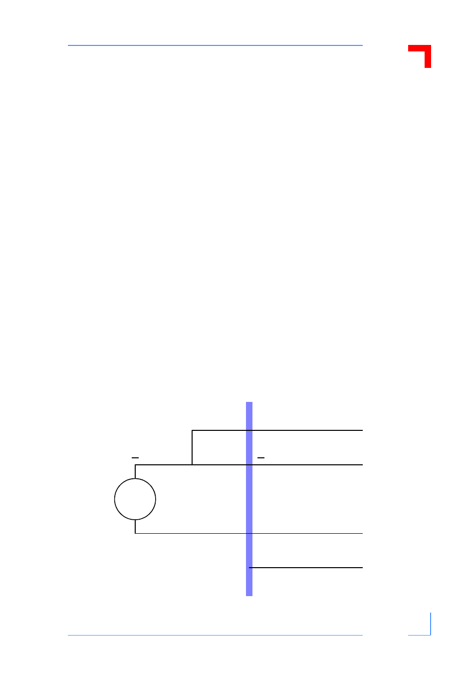
Single-ended Input Signals
Signals of this type are required to be connected: plus to plus; minus to minus. In addition the
minus pole must be connected externally to the analog ground of the CON2 connector. Refer
to the figure below for this type of connection.
Figure 4-1: Single-ended Input Configuration
V
Example for
channel 0
+
+
I
•
analog ground
•
CON 2
CP371
pin 21 or 42
pin 41
pin 20
pin 62
NC