1 system configuration, 2 driver software, 4 board diagrams – Kontron CP382 User Manual
Page 21: 1 front panel, System configuration - 5, Driver software - 5, Board diagrams - 5, Front panel - 5, Cp382 front panel - 5, Cp382 introduction
CP382
Introduction
ID 24208, Rev. 01
© 2002 PEP Modular Computers GmbH
Page 1 - 5
1.3.1
System Configuration
The external supply voltage (VCC) used as the output voltage on the CP382, must be within
the specified supply voltage range. In addition, it should be a DC supply with good ripple and
noise characteristics. Please refer to chapters 4 and 5 for further information.
1.3.2
Driver Software
The CP382 is supplied with appropriate driver software which provides software interfacing
with the system master.
1.4
Board Diagrams
The following diagrams illustrate board functionality and component layout.
1.4.1
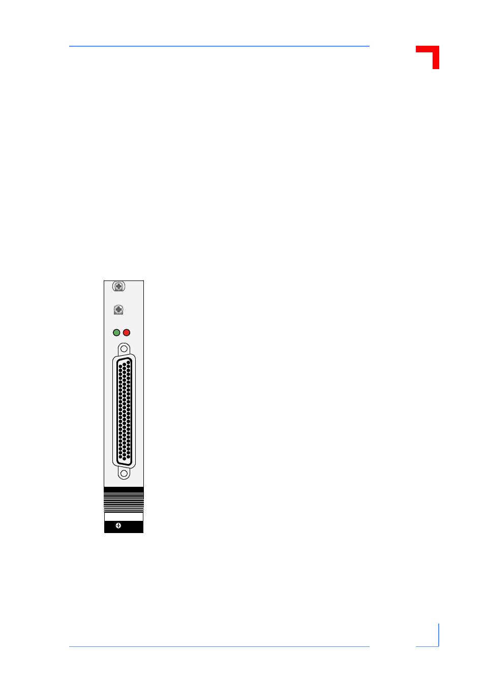
Front Panel
Figure 1-1: CP382 Front Panel
A green “Run” LED and a red “Fail” LED have been placed on the
front panel, to cater for the most likely use of these LED’s. However,
they are user configurable and may be employed for user defined
purposes.
CP 382
RUN FAIL