Elecraft P3 SVGA Instructions User Manual
Page 18
18
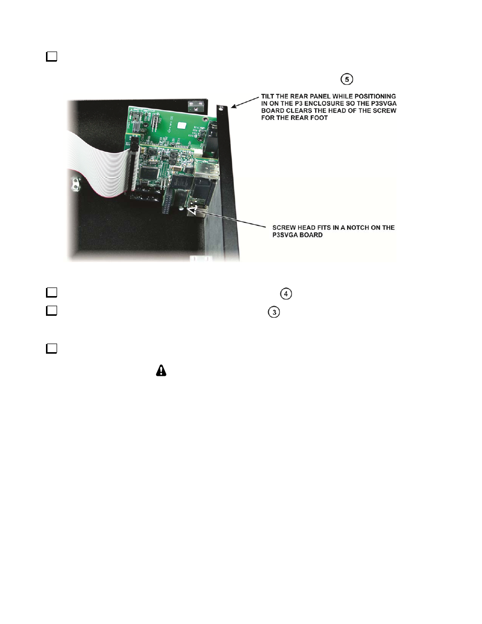
Replace the rear panel assembly on the P3 as shown in Figure 14. Tilt the assembly so the P3SVGA
board does not strike the screw head for the rear foot. The screw head fits in a notch on the P3SVGA
board. Secure the rear panel assembly with the screws you removed earlier (Figure 7
).
Figure 14. Replacing the Rear Panel on the P3.
Reconnect the TMP cable to the rear panel RF board (Figure 7
).
Replace ribbon cable in the clip on the side panel (Figure 7
). It is important that the excess cable
not be allowed to float freely in the P3 where it may be close to the RF board to avoid digital interference
on the P3 display.
Replace the top cover on the P3 with the notch to the rear using the screws you removed earlier:
REPLACE ALL THE SCREWS!
The P3's chassis strength depends upon all the screws being in place. Be sure to
replace all the screws and verify they are tight, but do not over-torque the screws.
That completes the installation of the P3SVGA option in your P3. Operating
instructions are on pg 5.
- KX3 Owner's Manual (58 pages)
- KX3 Assembly Manual (47 pages)
- KX3 Assembly Manual Errata (5 pages)
- KX3-2M (30 pages)
- KX3-PCKT (2 pages)
- KX3 Mobile Installation And Operation Guide (17 pages)
- KX3 Guide for Blind Operators (7 pages)
- KX3 Quick Reference (2 pages)
- K3 Programmers Reference (26 pages)
- KX3 Speaker Grille Instructions (9 pages)
- KXFL3 Filter Option (12 pages)
- KXFL3 Filter Option Errata (2 pages)
- KXAT3 (5 pages)
- KXBC3 (13 pages)
- KXPD3 (4 pages)
- Proset Boom Headset (1 page)
- PX3 Owner's Manual (53 pages)
- PX3 Owners Manual Errata (2 pages)
- KXPA100 Manual (55 pages)
- KXPA100 Assembly Manual (27 pages)
- KXPA100 Assembly Errata (1 page)
- KXPA100 Programmers Reference (24 pages)
- KXAT100 Installation Manual (17 pages)
- KX1 Manual (96 pages)
- KXAT1 (12 pages)
- KXPD1 (7 pages)
- KXB30 (8 pages)
- KXB3080 (20 pages)
- K1 (91 pages)
- K1 1.09 F/W (1 page)
- KNB1 Manual (8 pages)
- KAT1 Manual (15 pages)
- KFL1-2 (2 pages)
- KTS1 (1 page)
- KBT1 Manual (8 pages)
- KBT1 Manual Errata (2 pages)
- K1BKLTKT LCD Mod Kit (6 pages)
- K2 Owner's Manual (171 pages)
- K2 Owner's Manual Errata (1 page)
- K2 PLL (4 pages)
- K2ATOBKIT (15 pages)
- K2ATOBKT (2 pages)
- K2 Keying Modification Instructions (4 pages)
- KPA100 Manual (74 pages)
- KPA100 Shield Upgrade (3 pages)