Enabling the kxv3 module – Elecraft KXV3 Manual User Manual
Page 15
15
Replacing the Top Cover
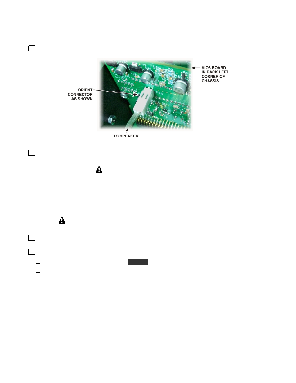
Hold the top cover above the K3, route the speaker wire under the stiffener bar and plug it into P25 on the
KIO3 board at the left rear of the K3 as shown in Figure 17.
Figure 17. Connecting Speaker Cable.
Position the top cover on the K3. Note that the tab on the back center goes under the rear lip of the K3 rear
panel. Secure the top cover with the nine 4-40 3/16” (4.8 mm) black flat head screws you removed earlier.
REPLACE ALL THE SCREWS!
The K3's chassis has excellent rigidity despite its light weight. The screws that hold the top
cover in place are an important part of the structural design. Please be sure to replace all the
screws and verify they are tight whenever you replace the cover or other panels
Enabling the KXV3 Module
Your KXV3 will not operate correctly until the following steps are completed!
Reconnect power and antenna (or dummy load) to your K3 and turn it on.
Refer to your Owner’s Manual and do the following:
Enable your KXV3 interface using the
CONFIG
menu.
Look under Calibration Procedures, Transmitter Gain, and perform the Milliwatt TX Gain Calibration
(KXV3) procedure.
This completes the installation of the KXV3 interface in your K3 transceiver.