Elecraft KXV3 Manual User Manual
Page 11
11
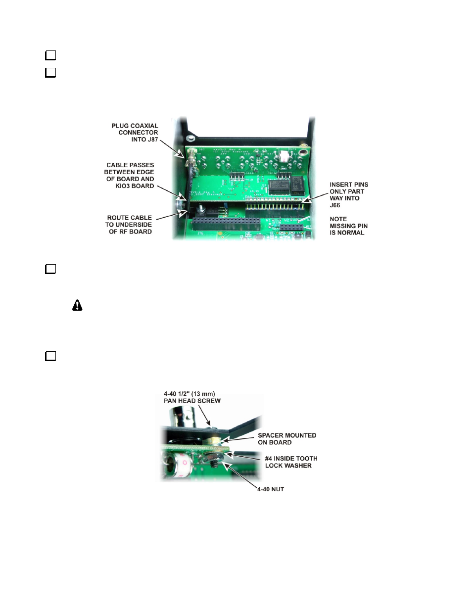
Fit the TMP coaxial connector onto J87 on the KXV3 board assembly (see Figure 9).
Thread the square connector on the TMP cable through the gap between Q3 and the side of the RF board,
then plug the KXV3 board assembly into J66 on the RF board with the four BNC connectors facing out through
the rear panel (see Figure 9). The pins will just clear the top of J66 when the BNC connectors are up against the
top of the opening in the rear panel.
Figure 9. Mounting KXV3 Board.
Push the connector pins into J66 only as far as needed so the holes in the KXV3 connector bushings are
aligned with the holes in the back panel as shown. These connectors do not fully mate and the bushings hold the
board away from the rear panel. .
As you install components and reassemble your K3, be sure all the screws are in place
and secure, but do not over tighten them. Failure to tighten all screws may result in poor
shielding of sensitive components, resulting in possible noise or birdies in the receiver as well
as other difficult-to-trace problems.
Mount the KXV3 rear panel over the BNC connectors using two 4-40 1/2” (13mm) black pan head screws
through the corner holes with #4 inside tooth lock washers and 4-32 nuts on the inside as shown in Figure 10.
Do not fully tighten the nuts yet.
Figure 10. Mounting Hardware.