Enabling and checking the filters, Caution – Elecraft K3 Crystal Filter Manual User Manual
Page 9
9
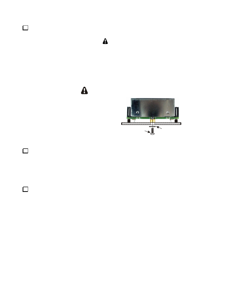
Turn the K3 upside down again and install the mounting screws and washers for each filter as shown in
Figure 5.
CAUTION
1) Use screws no longer than 1/4” (6.4 mm), as specified, measured from the flat surface
below the screw head to the end of the threaded shaft. Use your ruler to measure the screws
before installing them. Longer screws may extend into the filter unit and destroy it.
2) Do not over-tighten the screws. Too much torque may pull the threaded bushing out of
the bottom of the filter module.
4-40 1/4" (6.4 mm)
ZINC PAN HEAD
SCREW
ESD SENSITIVE!
WEAR A GROUNDED
WRIST STRAP OR TOUCH
AN UNPAINTED METAL GROUND
BEFORE HANDLING THE RF BOARD.
#4 INSIDE
TOOTH
WASHER
TYPICAL FILTER MODULE
Figure 5. Installing Filter Mounting Screws.
Replace the bottom cover you removed earlier, using seven 4-40 3/16” black pan head screws. Be sure to
replace all the screws securely, but do not over tighten them! Failure to replace all screws may result in poor
shielding of sensitive components, resulting in possible noise or birdies in the receiver as well as other difficult-
to-trace problems.
Enabling and Checking the Filters
Connect power to your K3, turn to the Crystal Filter Installation and Setup section of your Owner’s Manual
and perform the following procedures to set up filters you have moved or newly installed. You will need the
information you recorded in Table 1 to set up your filters.
• Filter Bandwidth Setup
• Filter Center Frequency Setup
• Receive Filter Enables
• Filter Loss Compensation
• Transmit Filter Selection