Elecraft K3 Crystal Filter Manual User Manual
Page 7
7
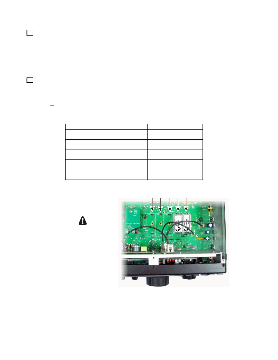
Look at the filters you already have installed. They are located just behind the front panel shield (see
Figure 3 showing two optional 8-pole filters installed). The filters must be installed in descending bandwidth
order with the widest bandwidth toward the FL1 position and the narrowest bandwidth toward the FL5 position.
You may need to move existing filters in order to preserve this order after installing the new filter(s). The
bandwidth is marked on each filter in Hz except for the KFL3B-FM filter. That is the widest bandwidth filter
available. If it is installed, it must be closest to the FL1 position. You can leave spaces blank to add filters later,
provided you maintain the order of widest to narrowest bandwidth with the widest nearest FL1 position.
Enter the following data on Table 1.You will need this information to set up your filters after reassembling
your K3. Be sure you’re following the rule described in the step above about the proper order for the filters.
Enter the bandwidth in the row opposite the filter position where it will be installed.
Enter the FREQ OFFSET shown on each filter. The optional 8-pole filters have no FREQ
OFSET marked on them. Enter a zero in the FREQ OFFSET column for those filters.
Table 1. Filters Installed.
ESD SENSITIVE!
WEAR A GROUNDED
WRIST STRAP OR TOUCH
AN UNPAINTED METAL GROUND
BEFORE HANDLING THE RF BOARD.
FILTER LOCATIONS
FL1
FL2
FL3
FL4
FL5
Figure 3. Crystal Filter Locations.
POSITION BANDWIDTH
FREQ
OFFSET
FL1
FL2
FL3
FL4
FL5